This is the wiki for products made by Fractal Audio Systems. Maintained by members of the community.
Amp block
Contents
- 1 Modeling amplifiers
- 1.1 Introduction to amp modeling
- 1.2 Amp modeling in the Axe-Fx III, FM9, FM3 and AM4
- 1.3 Firmware release notes
- 1.4 White-box modeling
- 1.5 Authentic or idealized models
- 1.6 Why your amp doesn't sound like Fractal Audio's reference amp
- 1.7 Oversampling, aliasing and latency
- 1.8 List of modeled amplifiers
- 2 Amp block
- 2.1 About the Amp block
- 2.2 Amp block in the AM4
- 2.3 Two Amp blocks
- 2.4 Preamp and power amp
- 2.5 Quick access to Amp block
- 2.6 Let's tweak
- 2.7 Amp controls
- 2.8 Low and High inputs
- 2.9 Amp gain
- 2.10 Clean up with guitar volume
- 2.11 Sustain and feedback
- 2.12 Midrange smoothness
- 2.13 Class-A mode
- 2.14 Power tubes mismatch
- 2.15 Ghost notes
- 2.16 Tube or solid-state rectifier
- 2.17 Acoustic coupling at low volume
- 2.18 Stereoizing amp output
- 2.19 Tube amplifiers information
- 2.20 Loadbox versus real speaker
- 2.21 Simulating other brands
- 2.22 Speaker cabinet resonance
- 2.23 Noise, fizz, crackle, sizzle, intermodulation, crossover distortion
- 3 Amp reset
- 4 General parameters
- 5 Tone / Ideal parameters
- 6 Preamp parameters
- 7 Power Amp parameters
- 7.1 POWER AMP MODELING
- 7.2 NEGATIVE FEEDBACK
- 7.3 PRESENCE FREQUENCY
- 7.4 DEPTH FREQUENCY
- 7.5 MASTER VOLUME CAP
- 7.6 MASTER VOLUME LOCATION
- 7.7 TRANSFORMER DRIVE (XFORMER DRIVE)
- 7.8 TRANSFORMER MATCHING (XFORMER MATCHING)
- 7.9 SPEAKER IMPEDANCE (VOICE COIL RESISTANCE)
- 7.10 PHASE INVERTER BIAS EXCURSION
- 7.11 CATHODE RESISTANCE
- 7.12 CATHODE TIME CONSTANT
- 8 Power Tubes + Cathode Follower (CF) parameters
- 9 Power Supply parameters
- 10 Speaker parameters
- 10.1 LOW FREQUENCY RESONANCE
- 10.2 HIGH FREQUENCY RESONANCE
- 10.3 TRANSFORMER LOW/HIGH FREQUENCY (XFORMER LF/HF)
- 10.4 SPEAKER IMPEDANCE CURVE
- 10.5 SPEAKER IMPEDANCE CURVES LIST
- 10.6 CABINET RESONANCE
- 10.7 SPEAKER DRIVE
- 10.8 SPEAKER THUMP
- 10.9 SPEAKER BREAKUP
- 10.10 SPEAKER COMPRESSION
- 10.11 SPEAKER COMPLIANCE
- 10.12 SPEAKER TIME CONSTANT
- 10.13 OUTPUT MODE
- 10.14 AUTO DYNACAB IMPEDANCE
- 11 Input EQ parameters
- 12 Output EQ parameters
- 13 Dynamics parameters
- 14 Legacy parameters
- 14.1 CATHODE FOLLOWER GRID CLIPPING
- 14.2 POWER TUBE EXCURSION TIME + RECOVERY TIME
- 14.3 CATHODE FOLLOWER TIME / RATIO
- 14.4 CHARACTER
- 14.5 MOTOR DRIVE
- 14.6 PI BIAS SHIFT
- 14.7 PICK ATTACK
- 14.8 TRANSFORMER GRIND
- 14.9 CATHODE FOLLOWER TYPE
- 14.10 DYNAMIC DAMPING
- 14.11 CATHODE FOLLOWER HARDNESS
- 14.12 DYNAMIC DEPTH + DYNAMIC PRESENCE
- 15 Videos
Modeling amplifiers
Introduction to amp modeling
Read A beginner's guide
for more information about Fractal Audio's amplifier and cabinet modeling.
Amp modeling in the Axe-Fx III, FM9, FM3 and AM4
The Axe-Fx III is the flagship product, offering the most complete feature set and two Amp blocks. It lets you choose between Best Quality
vs Minimum Latency
oversampling.
The FM9 provides the same amp modeling algorithms and quality as the Axe-Fx III, including two Amp blocks.
The FM3 provides the same amp modeling algorithms and quality as the Axe-Fx III and FM9, but due to its lesser processing power, it has a single Amp block and a few (non-essential) features are not included.
The AM4 provides the same amp modeling algorithms and quality as the above mentioned devices. It has a single Amp block. Some non-essential parameters are not available on the AM4.
FRACTAL AUDIO QUOTES
[1] […] We model things that other products simply cannot as it requires more CPU power than available. The Axe-Fx III dedicates an entire 1GHz DSP to just amp modeling. And this DSP is 2-4x more powerful clock for clock than typical DSPs. We even model esoteric things like the bias excursion in the phase inverter. And that's just one thing. There's dozens of other little things like that. Many that I can't talk about because they are secrets.
[2] Some of the amp models in the Axe-Fx III use 85% of the dedicated 1GHz DSP.
FM3:
[3] They are the same quality. Certain features were removed to allow the algorithms to run including the bias tremolo, input dynamics processing […]
[4] We removed all the superfluous stuff (bias tremolo, dynamic presence/depth, etc.) in order to get the core amp modeling to run on the slower processor.
[5] The Axe-Fx III contains various algorithms that allow you to enhance the amp modeling that don't exist on a real amp. I.e. dynamic presence/depth, input dynamic processing, etc. These were removed to allow the core amp modeling to run on the lower-powered processor.
AM4:
Regarding advanced Amp block parameters:
[6] The list is trimmed down a bit but the essential stuff is in there.
Firmware release notes
While Fractal Audio's processors also provide state-of-the art digital effects, the amp modeling is the flagship feature. Amp modeling is part of the device firmware. Each generation of Fractal Audio's amp modeling has a name such as G3, Ares, Quantum, Cygnus, or Cygnus X-2.
The amp modeling-specific parts of the Axe-Fx firmware release notes are highlighted on the Amp modeling release notes
page of the wiki.
White-box modeling
Fractal Audio's approach to modeling amplifiers is referred to as white-box modeling
. It means that every analog component is meticulously measured and digitally simulated, so that the model not only produces the sounds of the modeled amplifier, but also allows adjusting the controls like on the modeled amplifier.
Black-box modeling
refers to profiling or capturing the sound of an amplifier with the controls set at specific values. This is achieved with or without the help of neural networks, machine learning, artificial intelligence, etc., with product examples being Kemper, Quad Cortex, Tonex, and Neural Amp Modeler. This approach doesn't always include authentic behavior of the controls on the original amplifier.
In The technical modelling thread
Fractal Audio discusses modeling techniques.
FRACTAL AUDIO QUOTES
[7] I don't nitpick minor deviations in frequency response because no two amps the same. People listen to clips and it's always the same types of comments: "Clip A has more lower mids" or "Clip B has less high treble". Yawn.
What I do nitpick are the things that make a model sound and feel like a "real" amp. Anyone can get the static frequency response the same. That's easy. Do an EQ match. That's what everyone else is doing. Take a crude algorithm and do an EQ match to "fix" the inaccuracies. Yawn.
The hard part is getting the dynamic frequency response and dynamic gain response accurate. What makes a tube amp "breathe" and sound "organic" is the constantly varying frequency response and transfer function. That is extremely difficult to model accurately. It requires intricate knowledge of exactly how a tube amp works. Even profiling and AI approaches can't do that. All they do is learn a static transfer function. The problem though is that the transfer function is dynamic. The frequency response is constantly changing and the transfer function is continually changing as well. Our algorithms model that stuff. The frequency response and the transfer function are dynamic. The virtual power tubes for the AC30 models even go into Class-B operation if you drive them hard, just like the real amp. No black-box approach can do that.
Are our algorithms perfect yet? Probably not but in my not-so-humble and biased opinion 15.xx firmware was a significant improvement and has the "mojo" of a real tube amp.
[8] The stuff we are doing at this point is so advanced that measuring it is difficult. It doesn't show up using sweeps and pink noise because it's transient-related. Figuring out an analytic function to measure these things is half the battle (or more).
Matching frequency response is the easy part. Matching dynamic changes in overtone spectra is extremely hard and requires intimate knowledge of tube amps and measurement techniques on the bleeding edge of this technology.
[9] Using neural networks is possible but training a NN takes hours and requires hardware that a consumer modeler would not have (i.e. inference accelerators).
That said, my tests have shown that white-box modeling outperforms profiling and NN in terms of accuracy and aliasing. Whether that sounds "better" is subjective.
[10] I don't claim our modeling to be perfect, nothing is, but at this point it is highly accurate and I myself routinely fail a blind A/B test between the models and the reference amp into the reference speaker. More importantly, though, it simply sounds good and getting caught up in "it doesn't sound exactly the same as MY amp" is counterproductive. Make music, life is too short.
[11] There are a variety of reasons I'm opposed to all this profiling/ML/AI/etc. stuff:
- To fully sample an amp takes years/decades so in practice you only get a handful of snapshots.
- The data is opaque. You can't edit the data as there are no parametric relationships. It's just a bunch of data with no insight into what any of it means.
- Fundamental understanding of how an amp works is lost. Someone can make/sell a product that has samples without any understanding of why tube amps sound the way they do. The more people lean on this technology the more this knowledge will be lost to time.
- You can't make virtual amps. You can't design an amp completely in the virtual domain. You can only sample what already exists. So you can't make a virtual amp that does things that real tube amps can't do (i.e. FAS Modern).
- Guitar tone will never evolve. If we relegate ourselves to simply copying existing products we'll never evolve beyond that. We should be asking why did tube amps become the gold standard of guitar tone? Why did solid-state never gain widespread acceptance? What is it about tube amps that is pleasing? What can we improve upon? I have spent almost two decades now trying to answer those questions and I have some theories.
[12] […] We actually measure the amps and compare them to the models. The gain of an amp is an easily measured quantity and the models match the gains of our reference amps.
Now, our reference amps are always serviced before matching. Any resistors that are out of tolerance are replaced. Capacitors are replaced as needed and new tubes installed.
Old amps almost invariably have less gain than a freshly serviced amp. Tubes lose gain as they age. Resistors tend to increase in value as they age but this doesn't change the gain as much as the reduction in tube gain.
[13] […] Axe-Fx models use "ideal" values for all components, i.e. if a pot is spec'd as 1M the model uses 1M. We don't "tweak" the models to match the reference amp. We use the values as originally intended by the designer. That's why there will also be a slight difference between different copies of an amp and between an Axe-Fx model and the actual amp.
If a product's algorithms and models are accurate then the model should behave very closely to the real amp. That is the very definition of a modeler. […]
PREVIOUS GENERATIONS
[14] The hardest part of modeling an amp is getting the various controls to match the actual amp. If you don't care if the tone, drive, etc. controls behave the same it's much easier as we have software that learns the input EQ, output EQ and gain. The problem is then people go "the model doesn't sound the same as my amp if I turn the drive all the way up and bass all the way down".
So to accurately model the control behavior we need a schematic and the actual amp (as the schematics often don't indicate the pot tapers).
Truth is amps are more similar than people think. You can make almost any high gain amp sound like any other high gain amp with a few EQ tweaks which is basically what the designers do. For example a Bogner is basically a boosted Marshall with a different treble pot taper. Another popular new amp is basically just a JTM45 clone with a couple minor changes. In fact the schematic I got from the designer was a JTM45 schematic with markups. The scary thing I've learned is that a lot of these amp "designers" don't really even understand what they are doing. They don't have degrees in engineering and lack even basic circuit theory. They take existing designs and tinker with them changing circuit values. The basic topology of the amps are unchanged. So many of these new amps are nothing more than clones of old designs with some minor changes. Things you can do in the Axe-Fx with all the EQ options available.
There are only a handful of guys that really understand circuit theory and know what they're doing: Alan Phillips from Carol-Ann, Stevie Fryette, John Suhr, and several others. The vast majority are glorified technicians that are just making clones of existing designs with minor modifications.
A good example is the Marshall 18W. There are numerous clones and amps inspired by this design. The problem is that the original design is flawed. You can make that amp sound much better with some minor changes to the phase inverter (or grid stoppers) but none of these amps do that. They all use the same PI design which overdrives the snot out of the power tubes making the amp shift into Class-B operation resulting in fizz and crackling on the decay.
Authentic or idealized models
When modeling an existing amp, the choice has to be made to create an authentic or an idealized model. Fractal Audio's modeling is authentic, but idealized "FAS" models are also provided.
FRACTAL AUDIO QUOTES
[15] Accuracy, warts and all. Otherwise people compare against the real amp and say "it doesn't sound the same". The FAS models are idealized and have some of the "design flaws" removed or reduced.
[16] All our amp models are authentic.
[17] […] what I do is try to replicate a real tube amp as accurately as possible as that is the gold standard. Cygnus is demonstrably more accurate. I have the math and measurements that prove it.
IMO it makes playing the amps more enjoyable. It may make recording require some more work, just like you would with a real tube amp. I don't know as I haven't tried that.
For now if you don't like the changes go back to 15.01 or try some of the advanced tweaks. One of the things that Cygnus models more accurately is bias excursion and, in general, there is more bias excursion than before. You may not like the sound of bias excursion but it is part of what makes a real tube amp sound and feel the way it does. So one tweak to try is to reduce Master Bias Excursion or any of the individual bias excursion parameters.
The other thing with Cyngus is the power tube bias. The previous firmware biased the virtual power tubes a bit hot in comparison to real amps. This was necessary because of the algorithm to prevent unwanted crossover distortion. The new algorithms are more accurate and, as a result, the power tube bias matches the real amps. If you want that old sound increase the Power Tube Grid Bias. Try around 0.6 to start.
About multiple models of an amp:
[18] An amp model is basically a list of component values. If we were only modeling one amp, like this plug-in does, then having all the pull switches would be easy because behind the scenes you would just select a different list.
But when you are modeling hundreds of amps this becomes difficult.
Yes, from the user's perspective it could be simpler. Unfortunately it is what it is for this generation. Perhaps future generations will solve this limitation.
Why your amp doesn't sound like Fractal Audio's reference amp
FRACTAL AUDIO QUOTES
[19] The models in our products are based on our in-house reference amps. If a model doesn't sound like your version of that amp it won't sound like our reference amp either.
Why?
1. Component accuracy and drift.
The components used in tube amps are low-cost, consumer-grade parts. They typically have tolerances of 10% or more. Over time the value of these components drifts. If your amp is old chances are it doesn't sound like it did when it was new. All our old reference amps are given a thorough checkup prior to modeling with any out-of-tolerance parts replaced.2. Potentiometer tolerance.
A typical consumer potentiometer has a tolerance of up to +/- 20%. That's huge and that's end-to-end accuracy. On top of that the midpoint accuracy can be another +/- 20%. So if you have a 1M pot it could be as low as 800K. If it's linear it's midpoint should be 400K but could be as low as 360K. Now your 1M pot that should be 500K at halfway is only 360K. That's an error of 28%!3. Potentiometer taper.
A big one. Potentiometers come in a variety of tapers: linear, 30A, 20A, 10A, etc. The taper on an audio taper pot (i.e. 30A) denotes the value of the pot at mid rotation. For example a 1M, 10A pot would be 10% of its value at "noon", or 100K.
Manufacturers are constantly changing the taper of the pots in their amps. Sometimes the designer changes the taper as customers are reticent to turn knobs much away from noon. It's a weird psychological thing. Sometimes the manufacturer changes the taper due to availability concerns. Sometimes they change the taper when moving manufacturing locations. Sometimes they change the taper for no apparent reason at all.
Another factor is that almost all amps don't use true log taper pots. They use "commercial log" taper which is a crude approximation to a log taper. This is because true log taper pots are expensive. Fractal Audio products use true log taper. This means that '7' on your amp is not exactly '7' on the model even if the pot in your amp is exactly 1M and its taper is exactly 10A. Why do we do it this way? Because the response is smoother and if true log pots were the same price as consumer log pots everyone would use true log taper.
We model all amps assuming the pots are ideal. We assume the end-to-end resistance is exactly, say, 1M and the midpoint is, say, exactly 100K. We DO NOT use the values measured in our reference amp because no two amps are the same so we use the DESIGNERS INTENDED VALUE.
What all this means is '3' on your amp is not necessarily the same as '3' on the Axe-Fx.
Example: the Master Volume pot in a 5150 is a 1M, 15A audio taper pot. Theoretically it should be 150K at noon. On our reference amp it's about 15% low. If the reference amp's MV is set to '3' we have to set the model to around '2.5' to match. This is unsurprising due to the tolerance of the reference amp's pot.4. Indicator accuracy.
On many amps if you set a knob to noon it's not actually halfway in the pot's rotation. Why? Several reasons. Some amps are just weird. For example the Bogner Shiva's minimum rotation is around 6:00 and the maximum is around 4:00. So noon is actually past midpoint. Same with Soldanos. In other cases the knobs aren't oriented perfectly on the shaft. If it's a knurled shaft the knob may be off one tooth. If it's a smooth shaft then you're at the mercy of the human who put the knob on the shaft and tightened the set screw. This is why I prefer D-shafts. Finally the pot itself may be rotated relative to the panel.
You can try this yourself. Turn the knob on your amp fully CCW. Note the position of the indicator. Now rotate fully CW. Note the marker position. If it's an old amp it's probably not symmetrical.
Then there's the whole marking thing. Fender's are numbered 1-10. Soldanos go to 11. We use 0-10 so be wary of the amp's numbering.5. Power Tube Bias.
Another big one. The transconductance (gain) of a power tube can vary greatly. This is why power tubes are color coded, sold in matched sets, etc.
Amps come in two flavors: fixed bias and cathode bias. Fixed bias amps apply a "fixed" voltage to the grid of the power tubes. Cathode bias amps use a resistor between the cathode and ground to self bias the tube.
Most, but not all, fixed bias amps allow the user to adjust the bias point of the amp. This allows the bias point to be set to an optimum value for the particular set of tubes installed (since the transconductance can vary greatly). Some fixed bias amps do not allow adjustment. Examples are Mesa/Boogies, 5150s, and several other brands/types. The drawback of this is that the bias can vary greatly depending upon the gain of the tubes installed. Due to this the manufacturers err on the safe side and the bias is usually much colder than the ideal value.
Most cathode biased amps are not adjustable. Again you are at the mercy of the tube's gain but these amps tend to be biased hot to begin with and have higher transformer matching which prevents excursion outside of the S.O.A. (safe operating area).
If the bias is adjustable where the manufacturer decides to bias their tubes is a matter of preference. Most manufacturers bias their tubes on the cold side to prevent premature failure and reduce warranty claims. Especially the larger manufacturers.
This leads to the question of "what is the ideal bias point?" The pervasive school of thought is you adjust the bias so the idle dissipation is 60-70% of the tube's peak power rating. This is a safe approach and ensures that the tubes don't "red plate" and live fairly long and prosperous lives.
My opinion is that the ideal bias point is NOT a function of the tube's power rating. It's the point at which the power amp's transfer function is most linear. Unfortunately operating the tubes at that point can result in exceeding the tube's S.O.A. So the optimum bias point depends on the tube's power rating, the transformer primary impedance (matching) and the user's tolerance to tube replacement frequency.
For example, if we bias an EL34 based power amp at 60% peak dissipation it's actually running fairly cold. If we know that the transformer is slightly overmatched we can bias the tubes hotter, 70% or even more. This will result in a warmer tone but the tubes will wear faster.
What does all this mean? Well, I bias the virtual tubes on the warm side. EL34s are biased at around 70% because we don't have to worry about them wearing out. 6L6s are biased a little colder, around 60% but this is actually as "warm" as the EL34s because of the higher plate dissipation of a 6L6.
In practice this means that the models in the Axe-Fx will biased warmer than a new amp straight out of the box as most amps are biased cold (too cold IMO). After you wear the tubes out and bring it to a tech the tech will replace those tubes and bias them hotter than factory. So if you're comparing your new, out-of-the box 5150 with the Axe-Fx model the amp will probably sound "colder". Some people like this, many do not. If you like a colder sounding power amp it's just a knob twist away.[20] […] A potentiometer has tolerances, two of them. The first is the end-to-end resistance. If a pot is rated at 1Mohm, 20% then it's end-to-end resistance can be anywhere from 800K to 1.2M. The second is midpoint resistance. That same pot might be a linear pot which implies the midpoint resistance is 50% of the end-to-end resistance. Again, there is a tolerance on this value, typically about 10%.
Now, an ideal 1M, linear potentiometer will have a midpoint resistance of 500K. But a given amp may end up with a pot that is 20% low in end-to-end resistance and ALSO 10% low on midpoint resistance. So that pot is now 1/2 of 800K (400K) minus 10% which yields 360K. That particular amp will sound different than one that has a pot with tighter tolerances.
It's is therefore impossible for one amp to sound exactly the same as another copy of the same amp and, by extension, a model of the amp to sound exactly like a particular copy of the amp.
[21] […] If you take two copies of a particular amp and put all the knobs at 7, they won't sound the same. Likewise the model with all knobs at 7 won't sound the same either. However, the amps and the model will sound similar, very similar in most cases. We always assume the potentiometers in our models are ideal and have 0% tolerance both end-to-end and midpoint.
Another way of saying this is if you put a knob on the real amp at 7, our model with the knob on 7 will be as close as another random copy of that amp with its knob on 7 will be.
[22] The tolerance of potentiometers is terrible. You cannot set the knobs exactly the same as a given amp and expect things to match perfectly. For example, with BMT at noon on our reference 5150 I have to set the model's bass control to around 4.5 and the treble to nearly 6 to match. This is because the bass and treble pots are not perfect in the real amp.
Do a search on potentiometer tolerance. End-to-end and center. You'll be amazed at just how poor consumer grade "quasi-log" pots are.
Our models assume the pots are "perfect" and exhibit the exact resistance as specified. I.e. if it's a 1M 10A pot then it will be exactly 100K with the wiper at mid rotation. In a real amp the end-to-end resistance is +/- 20% and the midpoint can be off another 20%. Do the math and you'll see why no two amps sound the same at the same knob settings and why the model will not necessarily match a particular amp at the same knob settings.
I assure you that our model is accurate. You may have to adjust the controls up or down as much as 20% to match a given amp. That's the nature of tolerance. Listening to the clip I would say turn the bass up to 7 or more, turn the treble and mid down a bit.
[23] We actually measure the amps and compare them to the models. The gain of an amp is an easily measured quantity and the models match the gains of our reference amps.
Now, our reference amps are always serviced before matching. Any resistors that are out of tolerance are replaced. Capacitors are replaced as needed and new tubes installed.
Old amps almost invariably have less gain than a freshly serviced amp. Tubes lose gain as they age. Resistors tend to increase in value as they age but this doesn't change the gain as much as the reduction in tube gain.[24] Most people's experience is with amps that have aged. All our amps are brought up to original spec and all the tubes replaced before they are modeled.
Case in point: Deluxe Reverb Our reference Deluxe Reverb measured about 20% less gain before the tubes were replaced. This was partially due to the use of Groove Tubes in the reference amp. Groove Tubes tend to have a lower mu than a "normal" 12AX7A. The Groove Tubes were replaced with a different brand with a measured mu of approx 100 (as it should be).
Another factor is psychoacoustic. People perceive the models to have more gain because they listen at lower volumes and play harder as a consequence.
All our models are measured and have the same gain as the reference amps they are modeled after. Your particular copy of that amp may have more or less gain due to various factors including tube age/brand.
Oversampling, aliasing and latency
Read more about oversampling, aliasing and latency on the Latency
page.
FRACTAL AUDIO QUOTES
[25] Aliasing in important in every situation. Aliasing is the creation of harmonically unrelated and undesirable tones in the audible spectrum.
Aliasing is most easily heard when playing single notes. It is masked when playing chords but raises the effective noise floor causing a loss of clarity. IME it also causes rapid ear fatigue.
A real amp doesn't alias and good modelers have minimal aliasing. The most common way to reduce aliasing is to increase the sample rate either natively or by oversampling. You can also reduce aliasing using antiderivatives but this only works in very specialized cases when using waveshapers.
[26] […] The only way to avoid aliasing is to increase the sample rate. Double the sample rate and you double the computational cost. At a minimum. Often times this will quadruple the computational cost because it becomes O^2 operations.
Anything that does convolution-like processing (like a NN) will end up with O^2. I.e., if you double the sample rate the number of coefficients in an FIR doubles so you have to do twice as many operations for the FIR at twice the rate.
Anything that generates significant distortion should be oversampled (assuming 44-48kHz native sample rate) by at least 4x. That's an absolute minimum IMO. This would cause an increase of 16x computations.
[27] […] Any time you have a nonlinear transfer function you create distortion. In guitar gear the transfer function is usually some sort of clipping behavior. At the limit this turns a sine wave into a square wave. A square wave has harmonics that extend well into the ultrasonic range.
If you don't oversample enough those harmonics alias into the audible spectrum. No amount of hand-waving changes that. The correct thing to do is to increase the sample rate and then downsample after all the processing is done.
[28] Power amp modeling does not add latency.
List of modeled amplifiers
All current amp models are listed in the Amp models list
in the Wiki.
Most amp models have a dedicated factory preset.
Additional in-depth information about the amp models and original amplifiers is available in Yeks Guide to the Fractal Audio Amp Models (PDF)
.

FRACTAL AUDIO QUOTES
[29] We own every single amp that is modeled except for the Bludotone Ojai which we borrowed from Austin Buddy.
[30] I have close to 100 amps.
[31] I own almost every amp that we've modeled. I have a Dumble, Trainwreck, Ruby Rocket, multiple Carol-Anns, a Mark IIC+, a Mark IV, a Mark V, a JP2C, (2) Triaxis, about a dozen Marshalls, at least a dozen Fenders, etc., etc. I have two BE 100s: an original Purple one made when Dave was just a little shop and a newer one with all the latest changes.
We have a room with a pool table. You can't use it because there are amps stacked all around it and then more in the hallway and probably another 20 or so in my office. It's kind of ridiculous.
Amp block
About the Amp block
Axe-Fx III, FM9 — 2 blocks, 4 channels
FM3 — 1 block, 4 channels (Amp block shares a core DSP with the Delay blocks)
AM4 — 1 block, 4 channels
VP4 — n/a
ICONS — yes
Axe-Fx II — 2 blocks, X/Y
AX8 — 1 block, X/Y
FX8 — n/a
FRACTAL AUDIO QUOTES
Axe-Fx III:
[32] The reason I haven't added a third amp block is that I would have to reduce the oversample rate for all the amp blocks when three are in use and this would be detrimental to sound quality.
FM3:
[33] We could potentially do two amp blocks but at reduced quality and I don't want to do that. Part of the problem with other modelers is that they don't oversample enough (and use single-precision in places where you need double-precision). Then you get complaints of artifacts and ear fatigue and all the other things associated with inadequate sample rate and word length. The vast majority of users only use one amp block so we wanted to make something with one very high quality "Ares" amp block.

Amp block in the AM4
The AM4 displays the basic (authentic) parameters for each amp model. To get access to the advanced parameters, enter Expert Edit by pressing both Page buttons, or in the editor press Expert Edit.
Some non-essential parameters are not available on the AM4.
Two Amp blocks
One or more DSPs in the device is always reserved for the amp modeling. Therefore, adding a second Amp block on the Axe-Fx or FM9 to a preset, doesn't have a big impact on overall CPU usage.
The FM9 runs one amp per core. Two amp blocks require two cores. [34]
When using a single Amp block on the (discontinued) Axe-Fx II, the Amp block automatically runs at double the internal sampling frequency. The benefit of this is less aliasing in high gain models. Fractal Audio has not officially disclosed whether the sampling frequency is still tied to the number of Amp blocks in presets on the Axe-Fx III.
Some of the Factory presets on the Axe-Fx III and FM9 demonstrate the use of two simultaneous Amp blocks in a preset (i.e. Plexi+Vox).
Tips:
- Current firmware allows you to put two Amp blocks (if available) in series, instead of placing them in parallel rows. Previously this was advised against.
- When switching between two Amp blocks in parallel rows, make sure to set their Bypass Mode to Mute, to prevent bleed-through of dry signal from the bypassed Amp block.
- Adding a Drive block in front of only one of two Amp blocks in parallel rows, with both Amp blocks engaged, may cause phase cancellation because of increased latency in one row. Solve this by adding a bypassed Drive block to the other row.
- When using two Amp blocks to keep a stereo signal separated, use the Input Select parameter in each Amp block and set Balance in each block to one side.
- When using a single Amp block in a preset on a processor that supports two Amp blocks, use the AMP 1 block first.
Current firmware enables gapless switching of amp channels. See Gapless Changes
for more information.
FRACTAL AUDIO QUOTES
[35] All amp models have the same polarity so that you can mix them without weirdness.
Preamp and power amp
In a real amp, the preamp constitutes the amp's tone.
The power amp amplifies the weak output signal from the preamp, powers the speaker(s) and further sculpts the amp tone, especially when turning it up.
The virtual preamp and power amp operate the same as their hardware equivalents, but the power amp can't drive physical speakers without the help of a hardware power amp.
The Amp block consists of the virtual preamp and the virtual power amp. Parameters for both are provided.
Power Amp modeling can be disabled (globally or per-preset).
There's no way for the user to separate both sections into separate blocks. So, you can’t switch between (virtual) power amps for a given amp model.
If a simulated power amp without preamp is desired, for example when using an external preamp, use the Tube Pre amp model, with its tone controls set at default, and make sure that its power amp emulation is enabled.
For a preamp-only version of an amp model, turn off Supply Sag in the Amp block (pre-Cygnus) or turn off Power Amp Modeling in the Amp block (Cygnus and later firmware).
FRACTAL AUDIO QUOTES
[36] The Tube Pre model is neutral.
[37] It's not possible to run the power amp separately from the amp block though. It has nothing to do with proprietary technology or IP, it's an architectural limitation.
[38] It's not impossible but it has implementation difficulties. The main problem is that the amp block is nonlinear and therefore oversamples the data. Any effect inserted between the virtual preamp and power amp would need to also run at the oversampled rate which means many times the CPU usage. For example, if the amp block is running 8x oversampled then the CPU usage for any effect inserted would by 8x as much (I'm not going to disclose our actual oversample rate).
The other way is to downsample back to native sample rate, run the effect(s), and the upsample again. No problem right? Except the no-free-lunch theory gets in the way. Downsampling and upsampling add latency.
Quick access to Amp block
From the Home screen, double-click soft knob A.
Assign amp controls to a Performance page
.
On the AM4, access Amp Mode by pressing the middle switches.
Let's tweak
First, load the correct default parameters for the selected amp type by resetting the Amp block (see below).
The amp models for Band-Commander for clean tones and Friedman BE for dirty tones, both at default settings, provide great baseline tones. Combine them with the Cab IR Legacy #103 at default settings, and listen with headphones or through studio monitors. Or, compare to these reference sound clips.
Be aware that the choice of a cab (DynaCab/IR) in the Cab block often has much more impact on the tone than tweaking controls in the Amp block.
Use Snapshots
and Channels
to save and compare sounds.
Alternatively, use a far-field IR
to dial in the sound:
FRACTAL AUDIO QUOTES
[39] One of the things I've found really useful about these (far-field IRs) is they are a good starting point for dialing the amp block in. Near-field IRs can have excessive bass and/or treble. To compensate we might end up doing strange things in the amp block which throws off the distortion character and feel. When using a far-field IR it's very similar to how the amp sounds through a conventional cab.
So what I'm doing is using one of the far-field IRs to start, dial in the amp block and then choose a near-field IR. I then adjust the low/high cuts in the cab block rather than adjusting the amp block.
Adjust the Amp block parameters for the type of amplification hardware you'll be using:
FRFR
Power amp and traditional guitar speaker
Headphones, In-Ear Monitoring
FRFR + traditional backline rig
Recommended Amp and Cab settings for different types of amplification
Amp controls
Tone controls
- TONE CONTROL DISPLAY in SETUP = AUTHENTIC (default)
- Only the controls which are present on the actual amp are displayed on the main Tone page.
- When changing models, Bass, Mid and Treble will be reset to their default values to ensure accuracy for models that may not have these controls.
- TONE CONTROL DISPLAY in SETUP = IDEAL
- All tone controls are displayed, even those not present on the original amplifier.
Gain, Overdrive
The Amp block has Gain and/or Overdrive and tone controls, similar to the equivalent real amps. The range and behavior of those controls is the same as on the real amp, in current firmware.
If the real amp has two gain controls, the one closest to the 1/4" input is modeled as Gain in the model, and the other one is Overdrive.
Low Input, High input
If the real amp has two inputs, i.e. Low and High, the model is always based on the High input.
To get the equivalent of the Low input, change Input Trim to 0.500.
Tapers
The range of the Drive taper is 0-10.
Volume knobs on Fender amps go from 1 to 10. This translates to:
- Fender 1 = Axe 0.00
- Fender 2 = Axe 1.11
- Fender 3 = Axe 2.22
- Fender 4 = Axe 3.33
- Fender 5 = Axe 4.44
- Fender 6 = Axe 5.55
- Fender 7 = Axe 6.66
- Fender 8 = Axe 7.78
- Fender 9 = Axe 8.89
- Fender 10 = Axe 10.00
Also see Conversion Chart For Real Amp Settings vs. FAS
and Why Your Amp Doesn't Sound Like Our Amp
.
FRACTAL AUDIO QUOTES
[40] A typical pot used in a guitar amp has a tolerance of ±20%. On top of that there is the matching of the taper. The taper can also be off as much as 20% at the midpoint.
So if we take, say, a 100K linear taper pot that's perfect it will have a resistance of 50K at the midpoint. We assume perfect pots in the models. However an actual amp may have a pot that's low by 20% so that would be 80K. If the taper is perfect then it's only 40K at the midpoint (20% error). If the taper is off then it might only be 32K at the midpoint for a total error of 36% (!!!). To get the same response on the model you would need to set that control to 3.6 instead of 5.0. That's an absolute worst case and I've never seen that but I routinely see pots that are 20% off at the midpoint.
[41] I routinely see more than 20%. Full-scale resistance is often off by up to 20%. Mid-scale resistance is then off by another 10-20%. For example a 1M linear pot might be 800K and then off another 40K at mid-scale for a total error of 28%.
[42] It needs to reset all controls because not all are displayed. I.e. a Deluxe Reverb has no Mid control. For the authentic controls to work properly the Mid control needs to be set to its default position at noon.
[43] If a knob isn't present in the Authentic menu then it may not do anything in the Ideal menu.
[44] If a parameter doesn't exist in the Authentic controls there is no guarantee that the parameter in the Ideal controls will be functional.
[45] […] The sensitivity to pot value is very high. Consumer potentiometers have a 20% tolerance on end-to-end resistance and another 20% on midscale resistance. If the taper of the pot is Log10A and the pot is a nominal 1M then the midscale resistance should be 100K. If the pot is 20% low on end-to-end resistance (800K) and then another 20% low on midscale resistance then it's value at midscale would be only 64K. That's nearly half the nominal value.
The potentiometer values used in the models use "nominal" values. If the amp was designed with 1M pots then we use 1M for the pot value. When comparing the models to the amps I routinely have to change the B/M/T controls +/-20% to get the model to match the amp. And this is expected. For example on my 5150 I have to set the model's bass control to 4 to match the amp at 5 (-20%). This is unsurprising since when we measured the pot in the amp it was about 20% low at mid-scale.
[46] Most of the tweaks in an Axe-Fx / FM3 are circuit tweaks so it would be equivalent to modding your amp.
In the case of a Vibrolux the amp has a fixed midrange resistor in the tone stack. In the Authentic menu the midrange control is not there and the resistor value is fixed. When using the ideal page the midrange resistor is adjustable. This would be equivalent to modding your amp by adding a midrange pot.
[47] The only remaining non-authentic controls are the Mesa Mark EQ sliders I believe.
[48] The Mark series graphic EQ sucks. I know some people want authenticity but it's simply a bad design.
[49] […] A potentiometer has tolerances, two of them. The first is the end-to-end resistance. If a pot is rated at 1Mohm, 20% then it's end-to-end resistance can be anywhere from 800K to 1.2M. The second is midpoint resistance. That same pot might be a linear pot which implies the midpoint resistance is 50% of the end-to-end resistance. Again, there is a tolerance on this value, typically about 10%.
Now, an ideal 1M, linear potentiometer will have a midpoint resistance of 500K. But a given amp may end up with a pot that is 20% low in end-to-end resistance and ALSO 10% low on midpoint resistance. So that pot is now 1/2 of 800K (400K) minus 10% which yields 360K. That particular amp will sound different than one that has a pot with tighter tolerances.
It's is therefore impossible for one amp to sound exactly the same as another copy of the same amp and, by extension, a model of the amp to sound exactly like a particular copy of the amp.
[50] If you take two copies of a particular amp and put all the knobs at 7, they won't sound the same. Likewise the model with all knobs at 7 won't sound the same either. However, the amps and the model will sound similar, very similar in most cases. We always assume the potentiometers in our models are ideal and have 0% tolerance both end-to-end and midpoint.
Another way of saying this is if you put a knob on the real amp at 7, our model with the knob on 7 will be as close as another random copy of that amp with its knob on 7 will be.
[51] The tolerance of potentiometers is terrible. You cannot set the knobs exactly the same as a given amp and expect things to match perfectly. For example, with BMT at noon on our reference 5150 I have to set the model's bass control to around 4.5 and the treble to nearly 6 to match. This is because the bass and treble pots are not perfect in the real amp.
Do a search on potentiometer tolerance. End-to-end and center. You'll be amazed at just how poor consumer grade "quasi-log" pots are.
Our models assume the pots are "perfect" and exhibit the exact resistance as specified. I.e. if it's a 1M 10A pot then it will be exactly 100K with the wiper at mid rotation. In a real amp the end-to-end resistance is +/- 20% and the midpoint can be off another 20%. Do the math and you'll see why no two amps sound the same at the same knob settings and why the model will not necessarily match a particular amp at the same knob settings.
I assure you that our model is accurate. You may have to adjust the controls up or down as much as 20% to match a given amp. That's the nature of tolerance. Listening to the clip I would say turn the bass up to 7 or more, turn the treble and mid down a bit.
[52] There are many different types of "Log pots". Logarithmic potentiometers (more correctly known as audio taper pots) have "tapers". There are 5A, 10A, 20A, 25A, and 30A as well as reverse versions. The most commonly used tapers in guitar amps are 10A and 30A. The taper indicates the percentage of maximum resistance when the pot is halfway. I.e., a 1M 10A pot will be 100K at noon.
A pot labeled as 1MA doesn't indicate the taper and Mesa, in particular, doesn't like to divulge the tapers they're using. When I compared our reference Mark IV to our reference Mark V the tapers of the controls were different.
[53] […] For a Fender the controls go 1-10. On the model they go 0 - 10. To replicate the amp's controls multiply by 1.1 and subtract 1.1. I had the amp set to 6, 6, 6 and set the model to 6, 6, 6 and there was too much bass and gain. But the correct value is 5.5, 5.5, 5.5.
PREVIOUS GENERATIONS
[54] The tapers of the controls isn't really MIMIC per se'. It's just me doing the dog-work and measuring the tapers. So, in that regard, the tapers match my amps. However manufacturers are notorious for changing tapers, sometimes right in the middle of a production run due to part availability.
Furthermore the tapers in the Axe-Fx assume "true" logarithmic pots. Consumer-grade log pots are not true logarithmic, they're a crude approximation. At noon on a pot you'll get a nearly perfect match assuming the pot has 0% tolerance. As you deviate from noon there may be some error due to the approximation in the actual amp. As you get to the ends of the travel the error will decrease to zero. At any point there shouldn't be more than 10% or so deviation between the Axe-Fx knob position and the real amp.
Master Volume tapers are NOT matched. If they were the amp volumes would jump all over the place when you switched amp types. IIRC I use a Log10A for the MV.
MIMIC is distortion profile and frequency response matching. Hidden in the debug version of the firmware are special test tones and analysis modules that allow me to compare the real amp to the model.
[55] In most cases the knobs do translate. Usually within 10%.
[56] If the amp has no Master Volume, set the MV to 10 (the model will default to 10 when you select it). If the amp has no midrange control, set the MID to 5.00. If the amp only has a "Tone" control, set Bass and Mid to noon and the Treble control is your tone control.
[57] IMO accuracy is paramount and that's why we've devoted so much in resources to that end. The purpose of a modeler is to model amps as accurately as possible. Now it's impossible to account for component tolerances and tone controls can vary as much as 20% or more between two same amps. We therefore model all amps assuming the tone controls are "perfect" ((IOW if the amp was designed with a 500K pot we use 500K even if our reference amp is off by some percentage).
[58] Internet wisdom states that no two amps of the same type sound the same. That is true, but the reasons are far more simple than many would have you believe. Tales abound of esoteric effects such as wire dress, transformer orientation, phase of the moon, etc. And while these do have some effect, it is arguably inconsequential relative to the single biggest source of deviation: tone control tolerance.
I've spent the last ten years modeling tube amps and the number one thing I see is that tone controls are very inconsistent devices. First of all the tolerance of the control is typically 20%. That's plus or minus 20% so 40% total. A 100K pot can be as low as 80K or as high as 120K. This is contrast to the tolerance of a typical passive component which is 5% or less (usually much less IME).
Secondly the resistance at the midpoint can vary widely. A Log10A pot should be 10% of the resistance at midpoint. But, again, this can be off 20%.
Let's take the case of a bass control which is typically wired as a rheostat. On one amp the pot might be 10% high and the midpoint 10% high. Therefore with the control at noon (assuming, say, a 1M pot) the resistance will be 121K. Another amp off the assembly line might be 10% low. Therefore the pot will be 81K. That's a 40K difference between the two amps and that's not even worst-case.
Now you can make the amps sound the same by simply turning down the control on one and/or turning it up on the other.
So when your friend says "well, no two amps sound the same" you can explain to him that they are probably more similar than not and a small twist of the tone controls will bring them into agreement.
[59] You'll never get the knobs to correspond exactly. Commercial quality potentiometers are terrible. They vary widely in both end-to-end resistance and resistance at midpoint. Variations of +/- 20% are common (that's 40% total!!!). The Axe-Fx always assumes an ideal potentiometer, i.e. a pot where the end-to-end and midpoint resistances are exactly the specified value. Furthermore commercial "audio taper" pots are not truly logarithmic. They use a crude piecewise approximation. The virtual pots in the Axe-Fx are true log.
This is the #1 reason for the whole "no two amps sound the same". In fact they probably do sound the same but you need to adjust the pots on one (and possibly quite a bit) to make it sound like the other. For example if a tone control is at noon (5.00) on one amp you may need to set the other amp to anywhere from 3.00 to 7.00. This applies to any product that uses potentiometers, including drive pedals.
This also means when matching any virtual amp/drive/etc. in the Axe-Fx to a real-world counterpart that you may need to deviate significantly to get the same sound. For example, to get our reference Dual Rectifier's orange channel to match the model I need to set the model's treble control to around 4.0 (with the amp's treble at noon). This is because the pot in the amp has a significant deviation from the intended resistance at the midpoint. It's a 250K linear taper pot but it reads around 100K/150K when set to the midpoint. This is quite typical of commercial quality pots.

Low and High inputs
See Input Trim
and Amp Controls
for more information.
Amp gain
There are many ways to increase or decrease amp gain.
Important: Adjusting Input Level or Input Pad in SETUP does NOT affect amp gain!
- Guitar output
- Use your guitar's volume control. Also, the type of pickups matter.
- Input 1 Gain
- This control allows trimming the Input 1 gain to adjust for variations in guitar output level without having to adjust each preset. This is a global parameter.
- Input block level
- Increase or decrease Level in the Input block to adjust the signal strength entering the grid. You can also use channels for this. The Level parameter in each block before the Amp block also has an impact on the signal entering the Amp block.
- Drive block
- Insert a Drive block before the Amp block. Select a type such as FET Boost or Tape Dist for a clean boost and attach a pedal to its Drive parameter. Or set a Drive block to TS808 or something similar with Drive all the way down and Level turned up to tighten low end.
- Input trim
- Input Trim in the Amp block lets you decrease or increase the level of the signal going into the Amp block. The difference between the High and Low inputs on a Fender amp is around -6 dB, which equals to Input Trim at 0.500.
- Drive parameters
- Each Amp block has one or two Drive parameters controlling the amount of gain. You can assign an external controller to vary the gain.
- Master volume
- Increase Master Volume for more power amp distortion. Increase Mstr Vol Trim on the Advanced parameters page to increase the range of the master volume.
- Boost
- Engage Boost in the Amp block to crank the input level into the Amp block. Alternatively use a Filter or Volume block before the Amp block.
- Bright switch
- Engaging the Bright switch may increase gain with some models.
- Saturation
- Engage the Sat(uration) switch in the model.
- Pitch Follower
- Attach the Pitch internal controller to the Overdrive control. See Leon Todd's
5 minute tones - Pitch Follower
or the factory presetPITCH FOLLOWER
for a demonstration.
- Gain Enhancer
- Simulates the acoustic reinforcement of a loud amp coupling into the guitar which also adds gain. See
Output compression
for more information.
- Morph
- Morph between gain settings using two Amp blocks and Volume blocks. Cooper Carter's video
Axe-Fx III Live Two Amp Blending - 60 Second Sounds #1
has more information.
- Gain on low notes only
- See
Less distortion on low notes
.
Or select the Tape Dist type in the Drive block drive, set clipping mode to "HV tube", Drive moderate, Level as appropriate for the amp block it's driving, and you'll have another tube gain stage, complete with EQ. [60]
Cliff's Tech Note Understanding all the different gain controls
is very useful.
Clean up with guitar volume
FRACTAL AUDIO QUOTES
The amps clean up exactly like their analog counterparts. This is a common complaint with modelers because people use more gain because they listen at lower volumes. With a real amp the volume is loud which provides acoustic reinforcement to the guitar which enhances sustain. At lower volumes this is missing so people increase the gain.
It's actually one of the things we test when creating models. We even go beyond that. We compare the harmonic spectrum at various input levels as well to make sure the distortion characteristics change in the same way. And you can't do this with just a sine wave, you need to test both harmonic and intermodulation products.
Tech Notes: Clean to Mean w/ the Volume Knob:
[61] Here's a little trick to enhance the "clean up with guitar volume knob" thing.
In the Amp block go to the Dynamics page. Set the Compressor Type to Feedback. Turn up the Output Compression to taste. Notice that when you play harder the amp will distort more. Now you can use the Input Drive and/or Trim to reduce the input gain so that when you play softer or roll off the volume the amp will clean up.
Real amps get this from power supply sag but this requires the power amp be driven hard which can get muddy. This trick allows you to get that same response without cranking the Master Volume.
[62] To increase the "clean up with volume knob" lower the gain, set the Compressor Type to Feedback and dial in a bit of Output Compression. You can also use the Gain Enhancer mode which results in a more dynamic sound.
[63] One often hears pundits proclaim "Modelers don't clean up when rolling off the volume knob". While this may be true of some products we actually test and compare this to our reference amps. We measure the THD and output volume at different stimulus levels to ensure that the response is the same. The reason for this myth stems from acoustic feedback. Real amps are LOUD. Modelers are usually played at much lower volumes.
Consider the following diagram:
This is a block diagram of a model of what happens when playing a guitar with a speaker. Vg is the signal generator (your guitar). Sound waves from the speaker are fed back to your guitar and add to that signal. This signal is then attenuated by the the volume pot, k. The signal is amplified by the amp gain, A. Some portion of that signal is fed back, B.
The formula for a closed loop system like this is Acl = kA / (1 - kAB), where Acl denotes the closed loop gain. The open loop gain is given by Aol = kA.
Let's consider some examples.
In the first example let's assume the amp gain, A = 10, the volume knob is wide open, k = 1 and a mere 2% of the signal is fed back, B = 0.02. Using our formula we get: Acl = 10 / (1 - 10 * 0.02) = 12.5.
The open loop gain is Aol = 10.
That tiny 2% of feedback has INCREASED the effective gain by 25% (!!!). If the amp is approaching distortion then it will get more distorted.
Now consider what happens if we roll of the volume knob a bit. Let's assume everything else is the same but we set our Log10A volume pot to halfway which means k = 0.1. Now we get: Acl = 0.1 * 10 / (1 - 0.1 * 10 * 0.02) = 1.02 and Aol = 1
Rolling our volume knob to halfway now only gives a paltry 2% of gain increase for the same amount of acoustic feedback. So when the volume knob is wide open the amp has effectively almost 25% more gain than when rolled off halfway!
Now let's look at what happens when we lower the amount of feedback which would occur if we turned down the volume of our speaker. Let's leave everything the same but reduce our feedback to 1%.
Our first example with the volume pot wide open now becomes: Acl = 10 / (1 - 10 * 0.01) = 11.1 Aol = 10
And our second example becomes: Acl = 1.01 Aol = 1
So we see that the closed-loop gain is highly dependent upon the speaker volume. Simply reducing the speaker volume by 6dB lowers the effective gain increase considerably.
When playing with a loud amp the positive feedback from the speaker into the guitar effectively increases the gain of the amp when the volume control is wide open. As you roll the volume control off the amount of gain increase is lower. This gives the ILLUSION that the amp cleans up more when you roll of the volume but it's not the amp that is cleaning up, the signal into the amp is lowered more than if there were no feedback.
When using a modeler people almost always have the volume lower because amps are too loud. Lowering the volume reduces the feedback which in turn lowers the gain enhancement. To compensate people raise the gain of the model but now when you roll off the volume it doesn't clean up as much because the gain is higher. IOW, to compensate for the reduced feedback the user increases the gain, say, 25% to get the same effective gain as the loud amp but when rolling off the volume the amp gain is still 25% higher so it doesn't clean up as much.
P.S. An interesting result occurs if we let B = 0.1: Acl = 10 / (1 - 10 * 0.1) = 10 / 0 = infinity. This is what happens for controlled feedback. The closed loop gain approaches infinity and the loop becomes unstable and oscillates. That's why controlled feedback is easier to obtain at higher volumes, the feedback coefficient is greater. Another way is to move closer to the speaker. Since sound pressure is inversely proportional to the square of the distance moving 50% closer results in four times the feedback!
You can simulate this by using the Output Compression control and setting the Compressor type to "Feedback". It won't simulate controlled feedback. It does a good job of simulating gain enhancement.
[64] Cygnus SpectrumTrack(TM) ensures that the frequency response of the model matches the real amp at all levels of input excitation.
If you've played other products you may notice that the response deviates if you roll down the volume on your guitar. For example, the ****** gets noticeably more midrangey when you roll off your guitar volume. The ***** gets thinner. Etc, etc. This error in response also manifests when varying your picking intensity, especially for low- to mid-gain tones.
SpectrumTrack(TM) compares the model to the reference amp at a wide range of excitation levels and ensures that the model's response matches that of the reference amps.
Sustain and feedback
It should be as easy to get your guitar to feedback as it is with a traditional amp and cabinet, except when using headphones or IEM.
If you don't succeed, experiment with the Output Phase parameter in SETUP.
Alternatives:
HARMONIC FEEDBACK
factory preset- Mark Day's approach using the
Pitch Follower controller
- Simeon's feedback simulation,
demonstrated here by Leon Todd
Midrange smoothness
FRACTAL AUDIO QUOTES
[65] The "midrange smoothness" is actually adjustable in our modeling but it's hidden from the user. A real tube power amp clips hardest in the low midrange frequencies because this is where the trough in the speaker impedance is located.
At those frequencies (if the transformer is slightly undermatched, as is often the case) the grids clip before the plates. Grid clipping is very hard, almost a hard limiter. Plate clipping is much softer. We model all this but the grid clipping "shape" is hidden from the user and varies by model.
Many modeling algorithms, however, treat everything with a single nonlinearity and ignore grid clipping. This makes the midrange clipping softer and leads to a "sameness" across the spectrum.
The clipping in a tube power amp can be divided into three categories: Grid clipping. This occurs in the low midrange and is a harder distortion. Plate clipping. The plates clip at the speaker low frequency resonance and in the upper midrange frequencies and beyond. Plate clipping is softer. Transformer distortion. Transformer distortion is a complex distortion that increases with the inverse of frequency. It is sort of soft and farty.
Then there is crossover distortion which is not clipping but another form of nonlinearity.
The more nonlinearities you model, the more complicated the algorithm and the more CPU power required.
Then you get preamp distortion which is a whole 'nother can of worms.
Class-A mode
See Power Tube Grid Bias
for more information.
Power tubes mismatch
See Power Tube Mismatch
for more information.
Ghost notes
See Supply Type
for more information.
Tube or solid-state rectifier
See Supply Sag
for more information.
Acoustic coupling at low volume
See Output Compression + Type + Threshold + Clarity
for more information.
Stereoizing amp output
To create a broad stereo image out of a single amp, use one of the following approaches:
Enhancer block
Mic Distance parameter in the Cab block
factory preset PETRUCCI: emulation of TC Electronic Mimiq pedal
Michael Dolce's micro delay
Tube amplifiers information
Aiken Amplification maintains a collection of informative technical documents in their White Papers
page.
Among these is a glossary of common amplifier terms, also included in Dave Hunter’s The Guitar Amp Handbook
. Make Aiken's A Glossary of Common Amplifier Terms
your first stop when looking for a short explanation of something amp-related.
Recommended literature:
The Tube Amp Book
by Aspen PittmanThe Guitar Amp Handbook: Understanding Tube Amplifiers and Getting Great Sounds
by Dave HunterAmps! The Other Half of Rock ‘n’ Roll
by Ritchie Fliegler and Jon F. Eiche
Loadbox versus real speaker
FRACTAL AUDIO QUOTES
[66] The impedance of a real speaker cab changes slightly with the excursion. The low-frequency resonance decreases and shifts slightly. The inductance changes.
The low-frequency resonance changes because the speaker suspension goes nonlinear and the B * l product changes with displacement.
The inductance changes because the voice coil moves in and out of the magnet gap. The more turns inside the magnet the greater the inductance.
The are papers by Klippel et. al. that quantify the effects. FWIW, our products model this.
However... Jay is 100% correct that the linear differences are far more audible. Even two copies of a speaker in an enclosure will measure differently due to manufacturing variances.[67] Displacement is inversely proportional to frequency. As the speaker moves the voice coil moves in and out of the magnet gap. Inductance is proportional to permeability. The magnet is far more permeable than air. It doesn't take much displacement to significantly change the inductance. A 5mm change can reduce the inductance by 50%.
Simulating other brands
FRACTAL AUDIO QUOTES
[68] Our modeling is at "speaker level". DI captures and the outputs of other products are at "speaker jack" level. The sound from the speaker is slightly darker than the voltage at the speaker jacks. So comparing other products through the same IR will always yield a slightly darker sound with Fractal products.
Also other products use static speaker impedance curves. We use dynamic speaker impedance modeling. When a speaker is driven hard the impedance at high frequencies decreases and the sound becomes darker.
[69] The Axe-Fx III models are extremely accurate. The Kemper has its own vibe which a lot of people like. It's characterized by lots of midrange compression. You can replicate this on the Axe-Fx by setting the Output Compression type in the Amp block to Feedback and dialing in ~6 dB of compression. Adjust to taste.
The distortion of the Kemper is smoother than a real amp as well. You can replicate this by decreasing the Power Amp Hardness.
[70]
(Tone Match of a Kemper)
Turn off all effects in the KP.
Isolate the Cab in the KP. Then do an IR capture of it.
Turn on the Amp in the KP.
Dial in an amp that's close. Be sure to listen with the guitar volume turned up and down as you (though the KP won't behave like the amp did in this test, it will help you hear the amount of gain and also the pre-EQ.)
Then follow the cab with a Tone Match block if needed, using the instructions in the Tone Match Mini Manual.Method 2 is to use NO cab block in the Axe-Fx. Skip the IR capture and use a Tone Match block to achieve the match all at once.
Speaker cabinet resonance
See Low Frequency Resonance
for more information.
Noise, fizz, crackle, sizzle, intermodulation, crossover distortion
Noise
Fractal Audio's processors do not create or generate noise by themselves. Noise with high gain amp models is noise which enters the processor at the input and is then amplified by the processor.
FRACTAL AUDIO QUOTES
[71] Guitars make noise. Amplifiers amplify that noise. A noise gate will remove that noise WHEN YOU ARE NOT PLAYING. Expecting a power conditioner to remove noise at the guitar is illogical.
There are two types of noise guitars make: thermal noise (hiss) and interference (which isn't technically noise). You can't do anything to reduce the hiss aside from reducing the temperature considerably which isn't practical. You can reduce the bandwidth which will reduce the apparent noise but it may make the guitar sound dull.
You can reduce interference (hum and buzz and other periodic noises) in two ways: at the source and at the receiver (the guitar is the receiver). To reduce it at the source you have to find the source(s) and shield them, reduce the loop area, etc. At the receiver you reduce interference by shielding or using humbucking pickups or ideally both.
Computers are significant sources of interference. Computers with windows are especially bad. The inverse square law tells us that one way to reduce interference is to simply move further away from the source.
[72] Firmware cannot add or remove noise. Anyone having noise problems needs to look elsewhere in their system.
[73] They can hum do to tube imbalance but they don't add any thermal noise.
[74] There's not a modeler in existence that adds noise to match the noise of the amp being simulated. Noise is undesirable regardless of "realism". Hum and ghost notes are sometimes modeled but thermal noise never is primarily because the amount of thermal noise is partially dependent upon the resistance of the source (guitar pickup) which is a variable.
Furthermore any modeler exhibiting that much thermal noise would be roundly criticized for being excessively noisy.
[75] Gain doesn't add noise, it amplifies noise. SNR is determined by the hardware. There is equivalent noise at the input (engineering term is Noise Referred to Input). This is due to Brownian motion (thermal noise, also known as Johnson noise). That noise gets amplified.
The amp block is digital and adds no noise. It only amplifies (that's why it's called an amplifier).
To prove this to yourself, go into a noisy preset and disconnect the input to the amp block. The noise will go away because the amp block doesn't add noise. If it added noise you would still have noise at the output.
[76] I should add there are noise "reduction" techniques but all alter the desired signal in some way. Noise gates are among the most useful for our particular needs. Digital cameras use various techniques based on the statistics of the image (i.e. if an area of the image is monochromatic heavier filtering is applied).
The Intelligent gate in the Axe-Fx uses some crude statistical processing where the statistics are based on the typical stats of a typical guitar.
IOW, noise reduction is destructive. You can't beat the laws of physics. So you can't remove noise without somehow altering the original signal.
[77] The amp model doesn't add noise, it just amplifies it.
[78] To get the best noise performance it is important that the Instr In trim is set correctly in the I/O > Input menu. Set this as high as possible without clipping the input.
[79] Noise isn't modeled.
All preamp tubes have separate heating elements. This is called "indirect heating". Directly heated cathodes are no longer used except for rectifier tubes. Regardless direct or indirect heating has no effect on the noise floor. Noise is due to the random motion of electrons in a conductor. You can't "reject" it. You can lower the noise floor by keeping resistor values low (since noise is proportional to resistance) and by paralleling the input triode.
No modeler models noise. The dominant source of noise in any amp, whether real or virtual, is usually your guitar (or rather its pickups). A 10K ohm pickup will have -114 dBv of noise at room temperature. Modern A/D converters, when properly designed, can exceed this so the dominant source of noise is your guitar. This noise is then amplified by the amp (that's why they call them amplifiers). If the amp has, say, 60 dB of gain then that noise is now -114 + 60 = -54 dBv. Gain it up another 20 dB with the power amp and now you're at -34 which can be quite audible.
The situation gets worse as you roll off the volume in your guitar as you then introduce more resistance. A typical guitar pot is 500K ohms with an audio taper. If you roll the volume pot down to 8 or so you can easily introduce another 100K of resistance into the signal path. This will increase the noise to -94 dBv which becomes -14 after amplification. Really noticeable then.
Bottom line: if you have too much noise you have too much gain. Learning to play with less gain will improve your technique and the quality of your tone. Gain just masks poor technique and reduces clarity, string separation and dynamics.
Fizz, crackle
Fizz and crackle are terms to describe certain things people hear when playing an amp model.
- Fizz
- A high-frequency noise or hiss, which almost seems detached from the basic sound, floating above it. It's only there briefly after striking a chord or tone, like some kind of interference. Best heard when playing a model with power amp distortion.
- Crackle
- A side-effect of the initial attack, which halts but not gradually, it kind of stutters before it stops. Best heard when playing a clean amp model at high master volume.
People play through their Fractal Audio amp modelers, hear fizz or crackle, and think there must be something wrong with the modeling or their settings. In fact, they are listening to the realistic equivalent of a real amp, because real amps also generate fizz and crackle. You need to listen very closely to the guitar speaker to hear it. That's why you'll hear it better through a modeler, because these create a close-miked guitar sound when using cabinet modeling.
Fizz and crackle attribute to the authenticity of amp modeling. They also help to make the guitar stand out in the mix.
FRACTAL AUDIO QUOTES
[80] That's what amps do. You don't hear it through a guitar cab typically but using close-mic'd IRs it's more noticeable. You can reduce it by turning on the Plate Suppressor diodes. Trainwrecks have plate suppressor diodes for just this reason.
[81] The simplest way to remove fizz is turn down Master Bias Excursion.
[82] You're probably just hearing "tube crackle". This is most noticeable when letting chords ring out as the sound decays. It's more noticeable with FRFR because of the extended high frequency response of near-field IRs.
Tube crackle occurs when playing more than one note typically. When you play multiple notes (as in a chord or even a diad) the amplitude "bounces" around as the multiple notes reinforce each other or cancel each other. The result is an envelope that is not uniform. The peaks of the waveform clip but the troughs do not. This causes a crackling sound when you get on the edge of distortion because the points at which distortion occurs are far enough apart in time to be audile.
You can reduce it by softening the distortion. Reducing Preamp and/or Power Amp Hardness will reduce the crackling but this will deviate from authenticity.
[83] Crackliness of the note decay is dependent upon how hard the clipping is. If it's the power amp clipping this is dependent on the hardness of the power tubes (Power Amp Hardness) and the amount of negative feedback (less = softer). If it's the preamp clipping it's dependent on the hardness of the preamp tube (Preamp Hardness) and the negative feedback around the last stage (not user adjustable).
A JCM 800, for example, crackles like crazy because there is a lot of feedback on the last preamp stage (since there is no cathode bypass cap). A Friedman BE-100 preamp is similar to a JCM 800 but it has a cathode bypass cap on the last stage and the resulting distortion is much smoother.
[84] […] Listen to some isolated tracks sometime.
That fizz is desirable. Almost all high gain amps use a lot of feedback on the last triode stage to make it as "hard" as possible. This is typically done by using no cathode cap or a small cathode cap. You never see big cathode caps on the last stage of a high-gain amp. This gives lots of negative feedback and makes it clip harder. Another technique is to use negative feedback to the grid. This is done in 5150-based designs which makes the stage clip even harder. The last stage of a 5150 basically looks like a diode clipper.
The harder the clipping the more overtones that are created and the better the tone cuts. Without those overtones your sound is lost in the mix. Amp designers know what they are doing. Trust them.
[85] You're not going to hear the same thing through FRFR that you heard from guitar cabs. Your audience will hear something very similar but you won't. What you're hearing through FRFR is a mic'd representation of the cabs. It takes some getting used to. You have to start thinking like a producer/engineer rather than a guitar player. If you start trying to dial out what you call "fizz" and "artifacts" you're going to end up with a tone that doesn't cut. It might sound good to you but it won't fit in the mix. That fizz and sizzle is what makes those classic rock tones work. Listen to some isolated tracks of VH and AC/DC and you'll hear a ton of high-end sizzle. In the mix, however, it's not noticeable. If you remove it then the guitar sounds dead.
[86] Fizz on the decay is natural and it's what tube amps do. If you don't like it you can reduce the Triode Hardness but then it won't cut in the mix as well.
[87] […] when listening to things at a low volume fizz will be more noticeable. Power amp distortion can be particularly fizzy but we don't notice it because the amp is usually really loud when the power amp is distorting.
[…]
I was sitting in my chair about 3 feet from a 4x12 A/B'ing a JCM800 to the prototype Axe-Fx II some years ago. I was astonished at all the grit and fizz coming from the amp. The model was way too smooth. I sat there just playing a major 3rd interval listening to the crackle from the amp whereas the model did not have this. The big thing was the crackle on the note decay. The amp sounded like frying bacon as the note died out. It would go "gcchhhh crackkklleee bzzzzzz". I grabbed other amps and noticed the same thing from all of them.
It was then that I realized I had a lot of work to do and spent a couple years researching how to make a digital amp modeler replicate all that stuff.
All that stuff, though, gives you note separation and helps you cut in the mix.
It turns out that tube amps do strange things when overdriven and those old concepts of soft clipping circuits are wrong. Tube amps get nasty and clip very hard and very asymmetrically.
Crackling sound through FRFR:
[88] That's what amps sound like. Go put an amp in an isolation room with an SM57 on it. Listen in the control room. You'll hear the same thing. You don't hear it as much using a real guitar cab because the high frequencies are rolled off which softens the sound.[…]
You're probably just hearing "tube crackle". This is most noticeable when letting chords ring out as the sound decays. It's more noticeable with FRFR because of the extended high frequency response of near-field IRs. Tube crackle occurs when playing more than one note typically. When you play multiple notes (as in a chord or even a diad) the amplitude "bounces" around as the multiple notes reinforce each other or cancel each other. The result is an envelope that is not uniform. The peaks of the waveform clip but the troughs do not. This causes a crackling sound when you get on the edge of distortion because the points at which distortion occurs are far enough apart in time to be audile. You can reduce it by softening the distortion. Reducing Preamp and/or Power Amp Hardness will reduce the crackling but this will deviate from authenticity.
[89] I prefer the "fizz" on probably because I grew up with it. I just like the extra grit. When you're playing in a group context that grit seems to make the guitar cut better and fills out the sound. Without it things sound sterile.
I spent months trying to capture that. One day one of my employees came by the lab while I was working on the new algorithms. I was trying to explain the grit to him that I heard in my JCM800. "Hear that sizzle on top of the notes? Hear that raspy, bacon frying sound? That's what modelers are missing."
So I spent months figuring out where that came from and how to replicate it.
All IMHO...
[90] The "fizziness" of clipping is determined by how "hard" the clipping is. There are three primary places that clipping occurs in a tube amp: the preamp tubes, the phase inverter and the power tube plates.
Preamp tube clipping can range from soft to hard depending upon the design. Phase inverter (PI) clipping, which is actually the power tubes grids clipping, is very hard. Power tube clipping ranges from soft to hard depending upon the amount of negative feedback in the power amp.
Preamp tube clipping is comprised of cutoff, which is soft, plus saturation, which tends to be hard. Actual saturation rarely occurs because most preamp stages are designed such that the grid clips before the tube enters saturation. Grid clipping is hard. Local negative feedback is used in the form of cathode caps to shape the response of a preamp stage. If there is no cathode cap then there is negative feedback at all frequencies which increases the hardness of the clipping. The last stage usually dominates the clipping. Some amps have no cathode cap on this stage, e.g. JCM800, and therefore have hard preamp clipping. The Axe-Fx II does not expose the negative feedback settings for the preamp stages to the user, these are hard-coded. Reducing the Triode Hardness parameter will soften the clipping more-or-less depending upon the particular amp model.
In a typical tube amp the power tubes start to clip right about the same time the PI/grid clipping occurs. This is intentional so as to get the most power from the tubes. However some amps are intentionally mismatched as the designer's intent was to get more power tube clipping than PI clipping (i.e. Trainwrecks). The Transformer Match parameter adjusts the relative onset of power tube vs. PI/grid clipping. Lower values will cause the PI/grid clipping to occur before power tube clipping. Higher values will cause the power tubes to clip before the PI. Note that the power tube plates follow the impedance curve of the speaker so while the PI/grid may be designed to start clipping first, this only occurs in the midrange. At frequencies above 1 kHz or so the power tubes clip first since the voltage on the plates increases as a function of the speaker impedance. The first thing to clip tends to dominate as once you enter clipping the effect of clipping elsewhere is diminished.
Negative feedback around the power amp attempts to linearize the transfer function. The more negative feedback the more the power amp is linearized. However this also causes the clipping to become harder. A power amp with no negative feedback will go into clipping softly. As you increase the negative feedback the "knee" gets sharper. The Damping parameter is the negative feedback control. Higher values give more feedback and harder clipping.
Presence and Depth work by modifying the negative feedback. As you increase them the feedback gets less so by turning up the Presence you get softer clipping in the power amp.
Therefore to decrease the hardness of the power amp clipping: reduce Damping, increase Presence, increase Transformer Match. To reduce preamp clipping hardness reduce Triode Hardness. There is no parameter exposed to adjust the PI hardness.
HOWEVER, the relative hardness of clipping is not all that audible. You have to listen closely. The IR is far more important in the final result. Some IRs let through a lot more high frequencies and therefore sound more fizzy.
Furthermore overanalyzing this is inadvisable. Many amps are specifically designed to clip hard as this gives a more aggressive tone that fits better in the mix. Some amps actually attempt to increase the hardness of the clipping as much as possible by using diode clipping or using very high values of negative feedback (i.e. Modded Marshalls, Camerons, 5150 III). Listening at low levels fools your ear. Our ears are more sensitive to midrange at low listening levels. This means we hear the clipping differently than when listening at the actual level the real amp would be generating.
[91] There is a parameter to adjust how hard the grids are driven but it is not exposed to the user (FWIW that parameter is nearly at maximum for the Diamante Fire model. That amp absolutely obliterates the grids). There's also hidden code to use softer clipping models but, again, not exposed to the user.
Power tube grid clipping is nasty stuff but it helps cut through the mix. When listening in isolation using IRs, especially IRs made with dynamic mics (i.e. SM57), that fizz can be quite noticeable. As you can see from the plots the fizz is in the upper treble region.
- B There are several things you can try:
- Use a different IR that doesn't accentuate this region.
- Turn down the High-Cut Frequency on the IR.
- Reduce MV.
- Increase Power Tube Grid Bias.
- Increase Transformer Matching and/or Speaker Impedance so that the plates clip before the grids (plate clipping is smoother).
- Use a different amp model that relies more on preamp distortion.
I've contemplated for years a parameter that allows switching between "Authentic" and "Smooth" power tube clipping because this topic rears its ugly head now and then. But in the end I always stick to the "accuracy is paramount" philosophy.
Intermodulation, crossover distortion
FRACTAL AUDIO QUOTES
[92] Intermodulation is different than "ghost notes". IM occurs whenever two sine waves are passed through a nonlinearity (i.e. distortion). The nonlinearity causes the sum and difference of the input frequencies and their harmonics.
The human ear is slightly nonlinear so we hear a "beat" when playing two notes together. Put these two notes through distortion and the beat frequencies are amplified greatly.
Some RF circuits actually exploit IM as a method of demodulation. The RF input and a carrier are applied to a nonlinearity. The difference frequency is the desired baseband signal. This is mostly done at microwave frequencies where conventional mixing techniques aren't viable.
Ghost notes are a form of amplitude modulation . The cause of ghost notes is excessive AC ripple on the B+. The ripple modulates the gain of the output stage. Ghost notes are especially undesirable because they are harmonically unrelated and occur even when playing single notes. The cure is improved power supply and/or screen grid filtering. Some modelers model ghost notes. It is the opinion of this designer that any amp exhibiting ghost notes is poorly designed and/or needing repair and hence I don't model them.
[93] […] a "Tweed" amp has a cathode biased power amp. Most Fenders are fixed bias but some of the earlier ones, like the 5E3, are cathode biased.
Most cathode biased amps (often erroneously referred to as Class A) will go into Class-B operation when driven. Class-B operation creates crossover distortion. The reason a cathode biased amp goes into Class-B operation is because the capacitor in the cathode bias network charges up when the tubes conduct.
For example with no input signal the voltage on the cap might be, say, 10V. When each tube conducts more current flows from the supply which charges the cap up and increases its voltage to, say, 20V. The bias voltage has effectively doubled which means the tubes are now biased very cold and the amp runs Class-B.
When you stop playing the bias voltage settles back to 10V. Start playing again and the cathode cap charges up again. The time constant to charge the cap is on the order of milliseconds so it takes some time, it's not instantaneous.
Some amps use separate cathode networks to reduce the amount of bias shift, i.e. Matchless, Bad Cat, etc. but this increases cost.
The sound of Class-B operation is a raspy, fizzy, crackly sort of sound as crossover distortion creates a very different spectrum than clipping. Some people like the sound and there are actually pedals that intentionally create crossover distortion. Rumor has it that EVH liked his amps biased cold so he would get more crossover distortion.
Crossover distortion is mostly in the high frequencies. When listening to the proverbial "amp in the room" the high frequency rolloff of the speaker will mask it to a great extent. Close micing an amp yields a lot more high frequencies which will make crossover distortion more noticeable.
If you have an Axe-Fx you can experiment with the bias shift in these types of amps via the P.A. Cathode Resistance parameter. Turn it up and the bias will shift more resulting in more crossover distortion as the power amp is driven. Turn it down and the bias will not shift as much and the amp will remain in Class-AB operation longer. You can tell if an amp is cathode biased by the default value. If it is 0.0% then it's a fixed bias amp, otherwise it's cathode biased.
Some amps exhibit this more than others. The Suhr Badger has a lot of bias shift but it's still a great sounding amp, probably because the conjunctive filter rolls off the high end which helps mask the crossover distortion.
[94] Intermodulation is inevitable. To reduce it, reduce the gain, set bias points to 0 and reduce bias excursion.
[95] To reduce/eliminate crossover distortion increase Power Tube Grid Bias. A value of 1.0 will have no crossover distortion.
[96] Crossover distortion occurs when you play very lightly. To really hear the effect of crossover distortion turn the Power Tube Bias parameter all the way down and play lightly. You'll hear a scratchy sound. This occurs because the waveform gets a kink in it at the point where one tube stops conducting and the other starts. Some people actually like the sound and I've heard rumors that EVH liked his amps biased cold to get some crossover distortion. Output transformers can create a type of crossover distortion as well due to the BH curve being nonlinear at the origin.
[97] It's called intermodulation. No only do actual amps do this, ANY device that distorts the signal will do this.
[98] Blocking distortion occurs in older designs due to grid conduction. The grid gets forward biased which causes a net offset to develop on the coupling capacitor which, in turn, shifts the bias point. Modern designs incorporate various means of mitigating this (grid stoppers, for example). Some bias excursion is desirable though as without it the distortion can be "sterile".
[99] That's called "intermodulation distortion". It's the difference between the two frequencies. If you play, say an A 440 and and an Ab 415.3 the difference frequency is 440 - 415.3 = 24.7 Hz. If you do a double-stop bend the difference frequency will go down as you bend the note up. It's not something that "only an amp can do". Any nonlinearity will produce intermodulation distortion. It's a fundamental characteristic of nonlinear systems.
(firmware 27 for the Axe-Fx III) The new amp algorithms are more accurate than prior firmware releases. This creates various “artifacts” that real tube amps produce. These include low-frequency intermodulation distortion, “clutter”, spitting and other non-ideal behaviors. These behaviors, however, are precisely what gives tube amps warmth, dynamics and character. They go hand-in-hand. Without these, amp modeling sounds sterile and uninteresting.
[100] The "buziness" of IM is a function of the clipping hardness. […] determine whether you are getting power amp or preamp distortion. In general preamp distortion is softer but not always. It depends on the circuitry. You can reduce the clipping hardness with the Preamp Hardness and Power Amp Hardness parameters. This ONLY changes the shape of the virtual tube though. The final clipping behavior is also dependent on the surrounding circuitry which the user has no control over. For example a JCM800 preamp actually clips pretty hard because there is no bypass cap on the last triode's cathode. Therefore there is a lot of local negative feedback on that stage which makes the resulting transfer function "harder". In contrast a 1959SL Plexi has a bypass cap which softens the transfer function.
Power amp clipping behavior is dependent upon the amount of global negative feedback. The less feedback the softer the distortion. That's why "Class A" amps have softer clipping as they have no negative feedback. Fenders, otoh, typically have 3-6 dB of gain reduction which makes the power amp clip harder. Therefore you can reduce negative feedback to soften the clipping behavior if your distortion is coming from power amp overdrive.
[101] To put this to rest (again, for the umpteenth time)
One clip is the amp, the other is the model. All controls set the same. [102]
The reason that it's more "noticeable" with modelers is that there is a lot more high frequency content in a typical IR. When you listen to your tube amp through its speaker you are in the far field and usually somewhat off-axis. There is less high frequency content reaching your ears compared to what a microphone records. Go put your amp in an isolation room and listen to it through the control room monitors. You'll be astonished at what you hear.
[103] Amps do that. It's intermodulation distortion. It's more noticeable when close-mic'ing a speaker due to the extra high frequencies. Therefore it's more noticeable when using IRs.
[104] Vintage designs exhibit considerable bias excursion. This causes the duty cycle to change and introduces intermodulation distortion (IMD). IMD manifests as a low-frequency rumble (among other things). IMD, however, makes things sound warmer when rolling off the volume. Without some IMD amps can sound sterile, especially at lower gain. Turning down the Master Bias Excursion reduces the amount of IMD. You can also experiment with the Preamp Bias control and Cathode Follower parameters. Cathode followers introduce their own type of "clutter". The 5150 used a plate-driven tone stack with feedback to eliminate the clutter associated with a cathode follower. The 5153 uses a cathode follower but attenuates the signal prior to prevent overdriving the cathode follower thereby eliminating the clutter.
For more information see:
- Wikipedia's
Intermodulation
article - Aiken Amplification's
Crossover distortion
andBlocking distortion
Amp reset
Amp model parameters
Amplifier models, AKA “amp types”, are provided through the Amp block. An amp model presents itself in the Amp block through its typical name, and its specific settings.
Some of these specific settings are displayed in the Amp block. Some of them are hidden from the user. They are (probably) part of a table which gets interpreted by the firmware upon loading an amp model, together with the appropriate amp modeling algorithms. All available parameters are discussed in the owner’s manual and here in the wiki.
Disclaimer: the description above is a very simplified version of what's happening in the Amp block.
Why reset the amp
- Because you changed things...
- You can adjust settings in the Amp block, editing not only basic parameters like volume, gain and tone, but also many parameters that are more advanced. You can extensively tweak the sound and feel of the amp model to your liking. This is a unique feature of Fractal Audio’s amp modelers because of the use of
white-box modeling
, discussed above. - If you tweak the more advanced settings, you deviate from the default parameter values specific to that amp model. By resetting an amp model you make sure that the correct hidden and visible default settings for that amp model are restored.
- Because Fractal Audio changed things...
- Fractal Audio continually improves its technology through firmware updates. These firmware updates include improvements to the underlying algorithms and to specific amp model settings, based on those algorithms. This poses a challenge for existing presets.
- Changes to the core amp modeling algorithms are always applied, so the sound may change. There’s no way around this, meaning that there’s no support for older versions of core algorithms. If you want to stick to older algorithms, simply do not update the firmware.
- Specific Amp block settings, whether visible or hidden, are sometimes updated to new default values automatically when updating firmware that includes amp modeling improvements. And sometimes they are not automatically set to the new value, because some users want to keep existing values. The firmware comes with release notes that inform you about this, but, in general, there’s NO NEED to reset an amp after updating firmware, UNLESS the release notes say so.
- Resetting an amp model makes sure that the correct default settings for that amp model are put back in place. For example, to get a clean start, or to compare settings and sound.
What happens when you reset an amp
To accommodate users, Fractal Audio provides several methods to reset blocks, each with a different outcome.
The reset methods are:
- Re-select effect type
- Hard reset
- Soft reset AMP
The methods are explained below.
Note that a reset always resets parameters, not algorithms. About the difference:
- The latest firmware always runs the latest algorithms. They are implemented through firmware updates. As a user you cannot choose.
- The computational result of an algorithm can be manipulated through setting parameters. Like the Treble value in the Amp block. There are also hidden parameters. A preset is just a collection of parameters values.
- A reset of an effect, whether soft or hard, does not touch the underlying algorithm, it resets all parameters (incl. hidden ones) to their default values for the specific effect type.
Re-select amp model
This refers to selecting another effect type in the block and then re-select the previous one again (come back to the previous type). Or just select the current type again in the editor.
Note: this used to be referred to as soft reset. Later the Amp-specific soft reset command was added. To avoid confusion, let's now call it re-select.
When doing this, the model will be loaded again with most of its parameters returned to their default specific settings. It applies to the current channel of the block only. The preset needs to be saved afterwards.
Whether the bass, middle and treble tone controls amp are left untouched, or return to default when performing a soft reset of the amp, depends on the value of the TONE CONTROL DISPLAY parameter in SETUP:
- when set to AUTHENTIC: a soft reset of the amp will return Bass/Middle/Treble to their default values
- when set to IDEAL: a soft reset of the amp will NOT change the existing Bass/Middle/Treble settings
The list below describes what happens when performing this in the Amp block, page by page (the list refers to the editor, not the hardware UI), last checked in January 2024:
- Tone/Ideal
- Everything returns to default, except: Bass/Mid/Treble (unless TONE CONTROL DISPLAY is set to AUTHENTIC), Gain, Overdrive, Input Select, Bypass Mode, Level, Balance
- Preamp
- Everything returns to default, except: Boost Type, Boost Level
- Power Amp
- Everything returns to default, except: NFB Compensation
- Power Tubes + CF
- Everything returns to default
- Power Supply
- Everything returns to default
- Speaker
- Everything returns to default, except: Auto Dyna-Cab Imp., Speaker Compression, Speaker Time Const, Output Mode
- Input EQ
- Everything returns to default, except: Input EQ Type, Input EQ Q
- Output EQ
- Everything returns to default, except: EQ On/Off
- Dynamics
- Everything returns to default, except: Out Comp Type
Dedicated Amp Soft Reset
As of firmware 26.06 and equivalent firmware for the other products, a new SOFT RESET command has been added to the Amp block, on hardware and in the editor. It's also available in the AM4.
When executed, it resets everything, except the controls on the original that are available to the player. Gain, tone controls, master, depth, presence, speaker parameters, output EQ, etc. are left unchanged.
This single dedicated reset command ensures that an amp model uses the latest parameters values (visible and hidden), but doesn't touch specific settings that the user has dialed in.
You'll find this command on the hardware in the Amp’s Edit menu > Type > push-knob E. In the editor, this command is found in the Amp block's channel context menu.
The command works on the current channel only. To perform the dedicated soft reset on multiple presets and all Amp blocks in those presets, use the Amp Reset command in the editor's Manage Presets tool.
Here's an overview of what's reset to default and what's not:

Hard reset
If you want each and every parameter of the amp model to be returned to its default value, without exceptions, you need to hard-reset the model on the hardware or in the editor. This applies to the current amp channel only. The preset needs to be saved afterwards.
A hard reset lets you start 100% fresh, which is a good start when building a new preset.
On the hardware, select the Amp block, press EDIT, press RESET (soft knob A), which resets the current channel only.
In the software editor use, one of these methods:
- Select the Amp block, select the
Blockmenu at the top of the editor and selectReset Channel
- Right-click the Amp block (the context menu appears), click Edit and select
Reset Channel
- Select the Amp block, and press CTRL+I on Windows or Command+I on macOS
Note: Removing and adding an Amp block on the grid is NOT the same as a hard reset.
Refresh After New Firmware (RANF)
The software editors provide this menu option: Refresh After New Firmware
.
This is NOT a reset command. It syncs the software with the hardware. More information...
Reset a single parameter
You may assume that double-clicking a control in the software editor resets it to its default value, but that’s not the case. That value is just a generic default value, not necessarily the correct value for the specific parameter and amp type.
FRACTAL AUDIO QUOTES
[105] The correct value is the value when you reset the amp block. Double-clicking resets it to the "global reset" value which is zero. Ideally double-clicking should reset it to the correct value but this is a limitation of the architecture at this time.
General parameters
INPUT SELECT
From the Owners Manual:
The Amp block processes audio in mono. This control determines how incoming stereo signals will be processed. You can input only “LEFT” or “RIGHT” channels, or “SUM L+R” (the default setting).
Applications:
- Make two Amp blocks handle each side of a stereo signal separately
- Use a single preset with two guitars, each with its own Amp block (FM3: n/a)
The impedance input of amps is always fixed at 1M. Variable impedance is only used for pedal modeling.
FRACTAL AUDIO QUOTES
[106] Tube amp models are always 1M (no capacitor).
(OUTPUT) LEVEL
The Output Level parameter in the Amp block controls the outgoing level of the Amp block. It has NO impact on amp tone or gain.
This is the recommended control to set the overall level of a preset, to match it to other presets and to prevent digital clipping.
FRACTAL AUDIO QUOTES
[107] The amp block is always the place to set your volume. The Level control is repeated at several places in the amp block menus for convenience so you don't have to keep switching pages. The Level control has no affect on the tone.
You can never make the amp models the same volume for the same settings. It's a mathematical impossibility. It also depends on the guitar. If you make two amp the same volume at, say, all knobs at noon, then they may be drastically different if you simply change the Drive from 5 to 7. For example, take a Twin Reverb and a Dual Rectifier and match the volume with all knobs at default. Now increase the Drive to 7.0. The Dual Rec won't get much louder, just more distorted. The Twin Reverb will get much louder. Secondly, the signal strength from the guitar will affect the volume. If you were to make the volume the same between two different amp models and then use a guitar with weaker/hotter pickups the volume may be quite different.
Tone / Ideal parameters
This section discusses the controls which (may) appear on the Tone and Ideal tab pages. The Tone tab shows the authentic controls for the selected amp type. The Ideal tab shows every basic control, regardless of the selected amp type. Read Amp controls
for more information.
INPUT TRIM
From the Owners Manual:
Amps without an Overdrive control (below) will display Input Trim instead. This allows you to adjust for more or less preamp gain than the actual circuit being modeled. This is different from Gain in that it does NOT interact with the surrounding circuitry to change frequency response as it is varied. In short, use Input Trim to adjust gain without also changing tone.
Input Trim lets you adjust the range of gain of the amp by increasing or decreasing the signal level at the input of the Amp block. It's similar to Amp Gain in the system settings of the Axe-Fx II and AX8, and Input 1 Gain in SETUP on the Axe-Fx III, FM3 and FM9, but Input Trim operates per preset instead of global. The "Neutral" Input Boost type in the Amp block is also similar.
Values above 1 increase the level. Values below 1 lower the level. 1 is unity gain, 2 is twice as much.
Input Trim is different from the Drive controls (amp gain) in the Amp block, because it does not interact with the surrounding circuitry to change the frequency response as it is adjusted. Use Input Trim to adjust gain without changing tone.
In the Input Trim's modifier menu, a controller can be attached to create a variable boost, including Scene controllers.
FRACTAL AUDIO QUOTES
[108] Input Trim is something you shouldn't play with normally unless you want to deviate from the actual amp. Input Trim allows you to reduce or increase the gain of the virtual amps input buffer. This is analogous to changing the type of tube for V1 in an actual amp. Some people like less gain for V1 so will replace a 12AX7 with a 12AT7. Some people want a little more gain.
PREVIOUS GENERATIONS
Cliff's Tech Note:
The Axe-Fx II contains a parameter known as "Input Trim". This is just a straight gain control at the very front of the amp block. It has a range of 0.1 to 10.0 (-20 to +20 dB).So what use is a straight gain control at the front? Doesn't the w do the same thing? The short answer is "no". The long answer is "probably not".
On many amps the Drive knob, which may also be called Gain or Volume, has what is known as a "bright cap" across the physical potentiometer. This capacitor shunts high frequencies around the pot so that the Drive control is not a straight gain. It has an associated frequency response. As the Drive is turned down more high frequencies are shunted around the pot which results in a net treble boost. If the Drive is turned all the way down the treble boost is maximum, if it is turned all the way up the treble boost is zero.
The roots of the bright cap are due to manufacturers trying to compensate for different types of guitars. Guitars with single coil pickups tend to brighter but with less output. The user would then turn the Drive knob high on the amps. Conversely a guitar with humbuckers has more output but sounds darker. To compensate the user would typically turn the Drive down. This will result in a treble boost compensating for the darker response.
The Input Trim control allows one to fine-tune the amount of treble boost first and then adjust the amount of distortion. So it is probably more correct to think of the Drive control as a combination Drive/Treble control. With this in mind experiment with the Drive control combined with the Input Trim.
Indeed some manufacturers have actually implemented separate Drive and Trim controls on their amplifiers. For example the Fryette (VHT) Deliverance has two controls: a Gain knob and a Cut knob. The Gain knob has a bright cap across it while the Cut knob is just a straight volume adjustment. The purpose of these two knobs is exactly as described above.
[109] They (Amp Gain and Input Trim) are basically the same thing. The global amp gain has a smaller range as it's designed to be for fine-tuning between guitars whereas the local trim allows you to radically alter the response of the model. The local trim is equivalent to -20 to +20 dB.
Simulating the low input on an amp
If the real amp has two inputs, for example Low
and High
, the model is always based on the High input. Set Input Trim to 0.500 to get the equivalent of the Low input.
To translate Input Trim values to dB, use the formula: 20 * LOG10(trim value). In other words: calculate the LOG10 result of the input trim value, and multiply this with 20. Use the LOG10 function on a scientific calculator. For example:
- Input Trim at 0.500 = -6dB, because: 20*LOG10(0.5)
- Input Trim at 4 = 12dB, because: 20*LOG10(4)
Alternatively: every 2x multiplier = +6dB boost. So, Input Trim = 4.0 produces a +12dB boost.
See Translate scene controller settings to Input Trim values
for more information.
FRACTAL AUDIO QUOTES
[110] Be sure to set your Input Trim properly. If you are using single-coil pickups then you want to increase the Input Trim. This will optimize the S/N Ratio. With a properly optimized SNR the Axe-Fx has less self-noise than your guitar.
[111] 0.5 is equivalent to using the Low input jack on amps. If you are using high-output pickups it's often better to use the Low input to get into the sweet spot of the bright cap.
[112] All the models assume the "Hi" input on the amp was used if there are multiple inputs. If the amp has a Lo input this is typically half the sensitivity so you would set Input Trim to 0.5 to replicate. The beauty of Input Trim is you can set it to any value you like rather than being stuck with a switch with only two values.
It controls the voltage divider into V1. Many amps, for example, have two 68K resistors feeding V1. If you plug into the High input the resistors are in parallel and the gain is 1.0. If you plug into the Low input the resistors are in series and the gain is 1/2. Input Trim is a more flexible way of accomplishing the same thing but without being constrained to only two gain values.
INPUT BOOST
See Preamp parameters below.
MASTER VOLUME
From the Owners Manual:
The almighty Master Volume is a very important control. It determines the distortion and dynamics characteristics of the power amp simulator, and its setting at any moment can dramatically change the amp’s sound. As it is turned up, the tone controls will have less influence, and the sound will have more “bloom” and touch sensitivity. Settings for Master don’t necessarily correspond to knob positions on the amp being modeled. With a little experimentation, you will learn to dial in different great sounding Gain and Master combinations.
When you select an amp type, the Master will change to an appropriate/typical setting for that amp. If a real amp doesn’t have a Master, the “correct” setting will be applied i.e. “10”, or “wide open.” That's because vintage amps don't have separate gain (drive) and master volume controls. Therefore, Master Volume defaults to "10" in models which are based on these amps. Use Gain to control the amount of preamp gain/distortion as well as volume on non-Master Volume amp models.
- At high settings, less gain is usually required, especially for high-gain types.
- Amps designed for preamp distortion will typically sound great with the Master set low to prevent the tone becoming muddy or noisy. This includes the “USA Lead” types and others.
- Amps with negative feedback tend to have “crunchier” power amp distortion, which can get “raspy” when driven too hard. Experiment with the interactivity of Negative Feedback and Master on distortion tone.
- With Power Amp Modeling disabled, either globally or in one specific block, Master Volume becomes a simple level control with 40 dB of range.
- If more power amp gain is desired, Master Volume Trim in the Advanced menu can be used.
FRACTAL AUDIO QUOTES
[113] MV increases the power amp drive. If the power amp is distorting then the apparent volume will decrease as the MV is increased. It's impossible to predict how much the volume will decrease because it's dependent on dozens of other things like the Input Drive, BMT, pickup output, presence of Drive block, etc.
Regarding Firmware Ares 13.xx:
Added “Headroom” monitoring meter to Amp block. The most common reason for “muddy” tones with high-gain amps is incorrect setting of the Master Volume control. The Headroom meter displays the voltage at the virtual power tubes in dB. If the Master Volume is too high the meter will be near 0 dB most of the time. Note that this only applies to amps where the power amp is intended to run “clean” like the 6160, Recto, etc. Non-Master Volume amps get their distortion from the power amp distorting so this recommendation does not apply.
[114] Headroom meter:
It can't go above 0 dB. The headroom meter is how close the plate voltage is to ground. It can't ever be below ground so 0 dB is the maximum.[115] When the meter nears maximum the power tubes are clipping.
[116] […] you have to be very careful with the Master Volume. A Recto will start saturating the power amp in Modern mode at VERY low MV settings. Once the power amp starts clipping the tone will change.
With digital products I often see people set the MV higher than they would on the real amp because there are no sonic repercussions (i.e., pissing off the wife/neighbors, knocking Grandma's urn off the mantel, etc.).
If an emulation sounds darker or more midrangey than the real amp try turning down the MV. If it's a good emulation you should find a point (around 1-2) where you can hear the power amp start to saturate. Go up/down from there to get the desired power amp overdrive.
[117] Sag is also dependent on Master Volume. The higher the MV, the more sag.
[118] I just start low and bring it up until I get the desired compression. Then I chug the E string and if it's too buzzy or flubby I drop it down a bit. For tight, high-gain stuff you want to keep it low. For liquid, spongy tones you want to set it higher.
MV is the most important Amp block control for tone. You have to find the sweet spot. Start at 3 and increase until desired compression is reached. Stock presets are set to sweet spots, subjectively (based on the guitar used and personal opinion). Do not use MV for volume and don't turn it up too much (unless it's a non-MV amp). If an amp has Input Drive and Overdrive controls, use Input Drive for tone shaping and Overdrive as a flat gain control.
[119] As you increase the MV you drive the virtual power amp harder. As you drive the virtual power amp harder the frequency response becomes more dynamic, just like the real amp. And, just like a real amp, there is a sweet spot where the compression, dynamic frequency response, distortion, etc. just feel "right".
The particular settings for the sweet spot depend on the Input Drive, tone controls, etc. so there are no hard-and-fast rules. So, as always, use your ears. And don't be afraid to use your ears. You'll be a better player when you learn how the controls interact and how to find the sweet spot. The great players in guitar history new how to work their amps. They didn't rely on someone else to tell them where to set the knobs, they learned themselves.
[120] The way I dial in the MV is to turn up the MV until the amp stops getting louder. This is the point at which the power amp is saturating heavily. Then I back it off until I get the right amount of preamp and power amp distortion. That's the sweet spot where you get the tone and the dynamics. Too little MV and it's all preamp distortion and there's not much dynamics. Too much MV and the power amp is clipping too much and it can get flubby and/or harsh.
Just as with a real tube amp you have to get the power amp cooking to get the best tone and feel. Get that power amp working hard and the supply bouncing around and things get nice.
[121] Those amps (JCM, SLO) are all designed to get their character from power amp distortion. If you don't push the power amp all you are hearing is the preamp which is voiced to be trebly. The power amp then compresses the highs and the sound gets fatter.
[122] MV is the one knob that everyone should master (pun not intended). It sets the amount of power amp drive which, in turn, controls how much current is drawn from the power supply which causes the supply to sag. The trick is to find the sweet spot. Too much MV and it can get too compressed. To little and the amp will be stiff and too scooped. The MV works just like a real amp's MV except it won't get deafeningly loud if you turn it way up.
[123] One common theme with new users is the "blanket over the sound" complaint. Often this is due to excessive Master Volume values.
The Master Volume behaves just like the actual amps. However, unlike an actual amp, if you put it on 5.0 it won't cause your cat to hide for several days. This can cause the user to set the value too high as the physical feedback of painfully loud sound is not present.
As you turn up the Master Volume many amps get darker and the bass gets mushy. The key is to find the sweet spot.
Do this exercise:
Take an amp like the HBE. Set the MV to around 2.5 and turn the Level to a comfortable volume. Turn the Presence up to around 8.0. Copy the settings to "Y" by double-clicking the "Y" button. Now you have the same amp model and values in X and Y. Turn up the MV in Y to, say, 6.0 and lower the Level until the volume is the same. Go back and forth between X and Y and notice how much darker Y is.This occurs because the virtual power amp is distorting, and quite heavily. Due to the impedance curve of the virtual speaker load this causes the bass and high treble frequencies to clip but not the midrange. The result is, naturally, compressed bass and high treble which can sound muddy and indistinct. Modern MV amps are not designed to overdrive the power amp considerably. They are designed to get most of their distortion from the preamp and then adjust the MV until the power amp just starts to clip which is the "sweet spot".
Some amps, like the Recto Modern, will distort the power amp at very low MV values, around 2.0. In real life these amps are painfully loud at these settings but in our virtual world we are unaware of this because the Level control allows us to adjust the volume to any arbitrary level.
Some modeling products intentionally limit how hard their virtual power amps can be overdriven. Even with the MV on 10 the virtual power amp is not being overdriven that much. Of course this is unrealistic. Our modeling is accurate and with the MV on 10 you will get the same amount of power amp distortion as the real amp when set to 10. With this great power comes great responsibility and that responsibility is understanding how the control works and how to set it properly.
[124] A little trick you can do to get the "bounce" of high MV without the muddy bass is to reduce the LF Res value on the Spkr tab. This will reduce the amount of bass clipping in the virtual power amp allowing you to turn the MV up. You can also reduce the HF Res to reduce the amount of treble clipping.
[125] Boxy midrange is usually an indication of the MV being too high.
[126] That's precisely what happens when the MV is set too high. The highs and lows compress first, especially with amps like a Recto, when the MV is turned up.
PREVIOUS GENERATIONS
Amp models now default to a starting Master Volume setting when selected. Also, the proper setting for non-MV amps is now a Master Volume setting of 10.0. Non-MV amps, therefore, will default to a value of 10.0 when selected. If more MV drive is desired for non-MV amps, the new MSTR VOL TRIM parameter in the Advanced GUI page can be used to increase (or decrease) the Master Volume. The starting MV value for non-MV amps is roughly the “sweet spot” for the amp. This is the point where the power amp starts to contribute to the tone and feel of the amp. Decreasing the MV will typically cause the amp to get brighter and less compressed and increasing the MV will cause the amp to get more midrange focus and more compressed. As always, your ears should be your guide.
[127] All Axe-Fx models have been "modded" to include a Master Volume. Setting the MV to 10 effectively removes it from the circuit.
[128] I was helping a customer out yesterday. He was complaining about lack of feel and thinness. I asked him what his Master Volume was set at. He said 1.5. I asked "why so low?". He said "because that's where I set it on the real amp". I explained that the MV on the Axe-Fx has a much gentler taper than real amp and that 1.5 on the real amp is probably around 5 or more on the Axe-Fx. So he cranked the MV up and exclaimed "wow, that's what I'm looking for!".
The MV taper on the Axe-Fx is a Log15A taper. This means the output is 15% of the input when the "pot" is at noon. Most amps use a higher taper than this, say 30A or even a linear taper. This is done as a marketing ploy. The unsuspecting customer sets the MV to 2.0 and goes "wow, this amp is loud". Thing is the amp doesn't get much louder. This also makes adjustment difficult because most of your volume range is constrained to a small fraction of the dial rotation. The Axe-Fx uses a gentler taper so that you can fine-tune the MV easier.
So don't be afraid to crank that MV up. When the MV is turned up the virtual power amp works harder which causes the virtual power supply to sag which adds compression which adds feel. It also thickens up the tone when you play harder because the power amp is distorting. You'll get much better results if you learn to find the sweet spot. While playing, turn up the MV until the volume stops getting louder. At this point you are driving the power amp into heavy distortion. Now back off the MV until you get the desired tone and feel. With practice you'll learn to identify how much the power amp is being pushed and where the sweet spot is.
[129] If you want the best tones out of the Axe-Fx you should stop copying photos of knob settings and learn how the knobs work. MV is one of the most important knobs as it controls how hard the virtual power amp is driven. Learning to find the sweet spot is an exercise that will pay handsome dividends. Take the JCM800 model. Set the MV very low, say 1.0. Play for a while. The sound will be harsh and scooped with a stiff feel. Turn the MV up to 5.0. Notice how there is more midrange and a softer high-end response, more compression and a better feel. Turn it up all the way and it will get fuzzy and indistinct. A real amp does the same thing. Learning to dial in the MV is among the most important abilities to harness the most from your Axe-Fx.
The Master Volume (MV) controls how much signal level is sent to the power amp. Many vintage amps have no MV control and the power amp runs "wide open". Modern amps often get their distortion from the preamp and the Master Volume then allows the user to control the volume of the amp. The Master Volume in the Axe-Fx II, as well as on real amps, is probably the singular most powerful control in the amp block. As the Master Volume is increased the virtual power amp begins to distort. The virtual power amp also begins to sag and all sorts of beautiful magic occurs. The tone becomes more focused, the dynamic response changes, the note attack is accentuated, etc.
MASTER VOLUME TRIM
The MSTR VOL TRIM parameter on the Advanced page can be used to increase (or decrease) the Master Volume range.
From the Owners Manual:
Allows you to adjust the range of Master Volume. Increasing the value above 1.0 will cause more gain in the virtual power amp and vice versa.
FRACTAL AUDIO QUOTES
[130] Just multiplies the MV by the amount. You only need to use it if you want more power amp drive and your MV is already at 10. IOW, if MV is 10 and you set MV Trim to 2.0 then the MV will be 20.
GAIN, OVERDRIVE
Gain was previously named Input Drive.
From the Owners Manual:
Gain (previously "Input Drive") sets the amount of preamp gain/distortion. Used in conjunction with the Master Volume, Gain determines whether the sound will be clean, broken up, overdriven, or fully distorted. A treble peaker circuit found on the drive or volume control on many amps is also modeled. This can be heard as the low frequencies are attenuated more than the highs when the drive is turned down (and vice versa). For amps that have no Master Volume, Gain functions as the amp’s volume control.
Note that Input Drive and Overdrive are applied to the appropriate points in the circuit for the amp being modeled, i.e. prior to the last triode stage or prior to the third triode.
Some models have Gain and Overdrive controls.
If the real amp has two gain controls, the one closest to the 1/4" input is modeled as Gain in the model. The other one is Overdrive.
The range of the Drive taper in the amp modeler is 0-10. Volume controls on Fender amps go from 1 to 10, or 11 or 12. See Amp controls
for the translation of the real controls to the model.
You can attach a Scene Controller to Gain, and then use scenes to vary the amount of amp gain. Or use an internal or external controller instead. Note that with some amps models this bumps CPU usage.
FRACTAL AUDIO QUOTES
[131] Input Drive increases the gain amount as you rotate the knob clockwise. As the gain increases the tone is shifted from a treble and upper mid emphasis, which produces an up front sparkling tone, to a lower mid and bass emphasis, which produces a thick meaty tone. Overdrive increases the gain amount as you rotate the knob clockwise but with no alteration of the tonal balance. Different combinations of Input Drive and Overdrive settings will have a dramatic effect on the response of the amplifier and the personality of your instrument. It is easy to get familiar with the action of these controls and you’ll be amazed with your ability to make any guitar sound mellow, fat, soulful or aggressive.
[132] Input Drive is the modeled amp's gain, drive, volume, etc. control. It adjusts the attenuation at the input to the amplifier gain stages after the input buffer. On a Marshall Plexi, for example it is the "Loudness" control. On a typical Fender amp it is the "Volume" control. On many high-gain amps it is called either "Gain" or "Drive". On a real amp this is implemented using a variable resistor called a potentiometer. Many amps include a "bright cap" on the drive control which is a small value capacitor placed across the terminals of the pot that bleeds treble frequencies through as the gain is reduced. Sometimes this bright cap is switchable via a switch on the amp. Sometimes it is fixed.
[133] In a typical amp Input Drive is called various names (Drive, Volume, Gain, etc). It is the knob closest to the input jack. In many cases this potentiometer has a bright cap on it so the frequency response will be dependent on the knob position. In some amps there is also a second drive control. This is your Overdrive knob. It does not have a bright cap so it only affects the gain.
[134] Sometimes they're labeled Gain, sometimes Drive, sometimes Volume. On an Soldano X88 they're labeled "Preamp".
[135] They are at different places in the chain. Gain is typically after the input buffer. Overdrive is typically one or two stages later.
[136] Some amps possess an attenuation control between the later gain stages. Examples of the are the Mesa/Boogie Mark series, Dumble ODS and others. This control allows the user to vary the gain staging. The Input Drive can be turned up and the Overdrive turned down so that the earlier stages distort more and the later stages distort less and vice-versa.
[137] Some amps have complicated input drive circuitry that requires a lot of calculations. Adjusting the Input Drive control can result in crackling as the time required to recalculate the network is long. Don't attach a controller to the Input Drive on these amps.
[138] Takes a lot of math to calculate the Drive. Not a bug.
[139] No effect on latency. Increases CPU.
About jumpered channels:
[140] Even a small bit of capacitance difference at the inputs of these amps makes a difference. Our models assume a fairly short jumper cable (3-4 inches). In my tests just increasing the length of the jumper cable to 1 ft. changed the frequency response significantly. So if your Y-cable is more than a few inches long it will change things.
PREVIOUS GENERATIONS
From the Axe-FX II v10.10 release notes:
The Amp block now differentiates amps that have both Input Drive and Overdrive controls, i.e. Mesa Mark series, Dumble, etc. When a model is selected for amps of this type, the menu shows both controls. For other types the menu shows only the Input Drive control (which was formerly called simply “Drive”). The Overdrive control defaults to noon when amps with this control are selected. As such, any presets based on these amps may need to be updated as this control was not present previously and the amount of drive may differ now. Note that these two controls are applied to the appropriate point in the circuit for the amp being modeled, i.e. for Dumble-style amps the Overdrive is prior to the last triode stage. In Mesa Mark amps the Overdrive is applied prior to the third triode.
Depending upon the amp model it can take a lot of CPU to calculate the Input Drive network. Some amps have simple networks that are rapidly solved. Others, like the Hook Lead and Rhythm models have complex networks that require more math. If you attach a modifier to the Input Drive it is constantly recalculating the network which increases CPU usage.
OVERDRIVE VOLUME
Firmware 21 for the Axe-Fx III (and corresponding FM3 and FM9 firmware):
Added “Overdrive Volume” parameter to Dumble-type amp models (ODS-100, Two Stone, etc.). This is sometimes labeled “Ratio” or “Lead Master”. As the Master Volume on these amps often has a bright capacitor the Overdrive Volume control allows setting the Master Volume higher to counteract the bright cap and then lowering the power amp drive with the Volume.
FRACTAL AUDIO QUOTES
[141] Most, if not all, Dumble-style amps have a Ratio/Volume/Lead Master/etc. control so this makes the models complete in that regard. My Fuchs ODS 50 does NOT have a bright cap on the MV but it has an "Output" control for the overdrive channel that is in series with MV.
BASS + MID + TREBLE
From the Owners Manual:
While other modelers use simple filters to approximate amp tone controls, our products recreate the exact frequency and phase response characteristics of a classic passive tonestack. In most cases, knob positions can even be matched to settings on the original amps. (Though recognize that many types of amps were built inconsistently with different types of potentiometers from one run to another.)
Many models provide tone controls NOT offered on the original amp. For example, many amps have no Mid control. To faithfully simulate such amps, set controls they are missing to “noon” (or “0” if you are using the “ACTIVE” Tonestack Type). Of course, you may still adjust these “bonus” controls to achieve innovative tones.
The exact frequency and phase response characteristics of the tone stacks on the original amps are modeled.
If the real amp doesn't have one or more of these controls, like a Mid knob, leave it at the default (Mid: noon).
A few amp types have a single Tone control instead of the regular B/M/T controls. The IIC+ model has a Treble Shift control, which has the same effect as the FAT switch.
More information:
FRACTAL AUDIO QUOTES
Setting bass and treble to zero on a passive tone stack tells you nothing about the response of the midrange control. On a Fender setting bass and treble to zero turns the midrange into a volume control. On a Marshall it turns it into some weird highshelf/lowpass thingy. A passive tonestack is a very different animal than active tone controls with well-behaved frequencies. Download and play with Duncan's TSC to see the effects.
HIGH TREBLE
This parameter is named HIGH TREBLE in firmware Ares and later. It was previously called the Bright
knob.
It's a shelving filter between the preamp and power amp and can be used to darken or brighten the output of the preamp. It replicated the “Presence” control in the Mesa Triaxis preamp when set to negative values (the Presence control in the Triaxis is a high frequency cut shelving filter), before the Preamp Presence control was added to the Amp block.
Do not confuse this with the Bright switch, see above.
From the Owners Manual:
Think of this as an extra tone control, useful to add “zing” or tame harsh highs.
FRACTAL AUDIO QUOTES
[142] You can use it to add a little zing to a preset or remove harsh high frequencies. You can also use it to simulate the behavior of the Presence control on a Triaxis (which is really just a high cut). Turn it down to simulate "Presence" settings less than 10.
PRESENCE + HIGH CUT
From the Owners Manual:
Boosts (or cuts) the upper frequencies from the virtual power amp by varying the negative feedback frequency response. Increased presence can help a sound cut through.
Presence is a high-frequency tone control for the power amp section. It boosts (or cuts) the upper frequencies from the virtual power amp by varying the negative feedback frequency response.
Amps with no negative feedback circuits in their design cannot utilize a realistic presence control. Therefore, if Negative Feedback is set (manually or automatically) to “0”, Presence won't do anything anymore (in Cygnus
amp modeling firmware).
If Power Amp Modeling is turned off, Presence is disabled in current firmware.
The range (min/max) of the Presence knob in the model is the same as the range of the real Presence knob on the modeled amp.
Some models provide a Presence Shift
function, which models the pull shift “Lead Presence” control found on some amp models. Also, certain modeled preamps (Triaxis and Marshall JMP-1) have a preamp Presence control. In such cases, a power amp presence (P.A. Presence) control is also displayed in the model.
In current firmware the Presence control in the Amp block behaves like the actual amp, rather than an idealized version. And the Presence Frequency parameter is now a frequency multiplier rather than an absolute frequency as the frequency of the presence circuit depends on the Presence control position. The Presence Frequency parameter works by scaling the value of the virtual presence circuit’s capacitor value. Setting the Pres/Depth Type parameter to Active or Active Pres will override the authentic modeling and implement an ideal presence circuit with fixed center frequency.
Presence control is set to a default value when an amp model is selected. This is done because many amps, i.e. Double Verb, Deluxe Verb, et. al., have no presence control and the value should be set to zero for best accuracy. On the other hand some amps, i.e. Jr. Blues, 65 Bassman, et. al, have fixed presence networks. The Presence control will default to the appropriate value for these amps. For amps that do have a presence control, the Presence parameter will default to a value that is deemed typical for the model.
FRACTAL AUDIO QUOTES
[143] The Axe-Fx II presence operates just like a real amp and modifies the virtual power amp feedback. This actually does create a sort of "magic" since it changes the shape of the distortion vs. frequency. That's the advantage to the nonlinear feedback network that the Axe-Fx uses. Negative feedback makes the distortion transfer function "harder". The presence control reduces negative feedback at high frequencies. This increases the treble but also softens the transfer function so you get more highs but the softer distortion reduces the amount of harsh overtones.
[144] The presence "circuit" in the Axe-Fx does the same thing as the presence circuit in an actual tube amp. It decreases the negative feedback in the power amp at high frequencies. The net result is a boost in high frequencies. The gain of an amp with negative feedback is A/(1 + A*B) where A is the open-loop gain and B is the feedback. The presence circuit makes B a function of frequency (i.e. B -> B(s), actually B(z) in digital land) so there is less feedback at high frequencies. Therefore the gain is greater at those frequencies and approaches the open-loop gain. You can hear this as you increase the Damping since that increases the overall negative feedback. The presence control will have more effect as the Damping is increased. The Depth control does the same thing but on low frequencies.
[145] The effect of Presence and Depth is consistent with the behavior of the real amp and depends on the amount of negative feedback. As you decrease negative feedback the presence and depth controls have less effect (as in a real amp). Also, as you increase Master Volume the presence and depth may appear to be less effective (key word is "appear") as the power amp distorts more and this masks the effect of the controls.
A tube amp's presence control is basically a type of treble control. It affects a higher range of frequencies and operates on a different principle but the net effect is an increase in high frequencies. There is also a slight increase in distortion in the higher frequencies since the power amp becomes less linear for those frequencies.
[146] HiCut is dependent upon Damping, just like a real amp. Hi Cut is modeling the Miller capacitance at the input to the Phase Inverter. The more negative feedback, the less the Miller capacitance.
DEPTH
From the Owners Manual:
Boosts low frequencies from the virtual power amp by varying the negative feedback frequency response. It is set by default to an appropriate value when the amp type is selected, but this setting may be overridden.
Operates the same as Presence (see above) but it handles the low frequencies.
Like Presence, Depth is disabled if Power Amp modeling is disabled.
FRACTAL AUDIO QUOTES
[147] Excursion = Depth. Manufacturers like to give this control fancy names (Excursion, Whomp, Resonance, etc., etc.) but it's just a Depth control.
[148] Depth = Resonance = "Whomp" = whatever colloquialism the manufacturer can think of. Depth differs from Bass in that it is applied in the power amp as opposed to the preamp. It is done by modifying the feedback network. Less lows are fed back thereby increasing bass response in the power amp. It is analogous to Presence except it affect bass instead of treble.
[149] Many amps have no depth circuit, e.g. Fenders, most Marshalls, and generally most older designs. In these cases the Depth knob will default to zero indicating the amp has no depth circuit.
Some amps have a fixed depth circuit, e.g. 5153, Freidman BE/HBE, Dirty Shirley, TripTik, Tucana, et. al. In these cases the Depth knob will default to a value that corresponds to the fixed circuit.
Finally some amps have a variable depth circuit, e.g. 5150, Diezel, et. al. In these cases the Depth knob defaults to a non-zero value that I think sounds good but that's just my taste.
The choice of IR and the monitoring system can greatly influence the amount of perceived bass. The desired amount of bass is a preference. If you are into "classic" tones then a Depth of zero would be a logical choice.
[150] Depth does not work at a Damping of 0 since Depth modifies the feedback and there is no feedback.
[151] The effect of the Presence and Depth is consistent with the behavior of the real amp and depends on the amount of negative feedback. As you decrease negative feedback the presence and depth controls have less effect (as in a real amp). Also, as you increase Master Volume the presence and depth may appear to be less effective (key word is "appear") as the power amp distorts more and this masks the effect of the controls.
[152] I look at the Depth knob as a starting point. Just because the 5153 has a fixed depth circuit doesn't mean you can't adjust the knob. The only reason that it is fixed on that amp is there wasn't enough room to put in separate knobs for each channel. The 50W version has an adjustable Depth (it's called resonance and the knob is on the back). The original 5150 had adjustable Depth. The designers choice isn't necessarily best. It depends on the cabinet (or IR) and your personal preferences.
Short answer: use your ears. I think too many people are scared to use their ears. But if you constantly rely on the ears of others you'll never learn how to create your own signature sound.
[153] Depth is dependent upon the speaker load. If your load doesn't match the internal speaker impedance curve exactly the response will be different.
When I'm testing amps I have a special speaker impedance curve I use that is derived from the particular LB-2 that I use. The curve included in the firmware is a typical LB-2 response. Due to component tolerances the resonant frequency and magnitude can vary as much as 20%.
Furthermore with the depth all the way up it is easy to start overdriving the power amp in the bass range. Again, due to pot tolerances the amp may be overdriving more or less than the model for a given MV setting.
[…]
I should add that Depth is also dependent upon the open-loop gain of the power amp which, in turn, is dependent upon the transconductance and bias point of the power tubes.
Therefore different power tubes and bias point will also affect the amount of low-frequency boost.
CUT
From the Owners Manual:
Reduces the amount of low frequencies coming into the amp simulation. This can be used to achieve a “tighter” tone or to reduce low-end “flub”.
This first-order shelving filter (high-pass) at the input of the Amp block defaults to 120 Hz. The frequency can be adjusted through the Low Cut Frequency parameter.
Note: Cut is the same as increasing Low Cut on the Input EQ page (see below).
FRACTAL AUDIO QUOTES
[154] You can use a Filter block before the Amp set to Shelving if you want to add more flexibility to what the Cut switch is doing in the Amp block.
[155] 120 Hz is where most amp designers put it. A typical cathode bypass has the pole at approx. 85 Hz. Assuming 6 dB gain reduction that puts the center frequency at 120 Hz.
[156] The bass cut switch is before the distortion so it will change the feel and breakup characteristics. The bass cut is basically intended to give you that Tube Screamer with Drive on 0 sound without having to use a dedicated Drive block.
[157] Cut engages a lowshelf filter at the input. This would be analogous to partially bypassing the input buffer cathode on a tube amp.
FAT
From the Owners Manual:
Emphasizes midrange and adds “body” by shifting the tonestack center frequency.
This is similar to the FAT switch on a Mesa Boogie, which is a popular control for lead tones because it adds body to the tone.
FRACTAL AUDIO QUOTES
[158] The Fat switch simply alters the tone stack treble capacitor. So the effect depends on the location of the tone stack.
[159] The Fat Switch multiplies the tone stack treble cap by four. Depending upon the type of tone stack, tone control settings, position, etc., etc. the effect can be more or less noticeable.
[160] The Fat switch changes a value in the tone stack which changes the response of the stack, shifting the mid dip down and making it less pronounced. The Tonestack Freq. parameter frequency scales all the reactive components in the tone stack which is something quite different.
BRIGHT SWITCH
From the Owners Manual:
Many amplifiers contain a “treble peaker,” included as a pull or toggle switch, or even hard- wired. Each amp type includes this control (even if the original mode does not). The effect may be subtle or quite pronounced depending on the amp type. This is also affected by the Bright Cap setting. If the original amp had no bright circuit, Bright is OFF by default but can still be turned on to apply circuit values suited to an amp of that general type. If the amp has a hard-wired treble peaker, the default state is ON.
The Bright switch is not to be confused with High Treble which is a shelving filter between the preamp and power amp (see below).
The Bright switch is either:
- the virtual equivalent of a bright switch (pull or toggle) on the real amp.
- the virtual equivalent of a bright cap on the volume or gain control of a real amp.
- the virtual equivalent of a hard-wired bright switch inside the amp.
- a method to change to the Bright channel of the original amp (if the original amp has a Normal and a Bright channel/input, and only the Normal channel/input has been modeled).
Bright caps are used to compensate for guitars with weak pickup loads, increasing treble as gain is decreased. It also changes the mids, which affects gain too.
If the modeled amp has a hard-wired treble peaker, the default state of the virtual Bright switch is ON.
Turning up the amp's Drive or Master may decrease the impact of the Bright switch, depending on the amp type.
The effect of the Bright switch on the tone can be controlled through the Bright Cap value parameter.
Some amp types, such as a Plexi, have a very high Bright Cap value, which has a large impact on the amount of gain.
FRACTAL AUDIO QUOTES
[161] If an amp doesn't have a bright switch, the operation of of the models' bright switch is undefined. I chose what I considered a reasonable value for the bright cap but if that doesn't satisfy the user then they are free to change it to a different value.
[162] The Bright switch always controls the bright cap on the input volume.
[163] The Bright switch switches in/out one or more capacitors on the Input Drive network.
[164] The Bright Switch models the "bright cap" across the drive/gain/volume/comodjulator pot. Some amps have no bright cap, some amps have a hardwired bright cap and some amps give you a switch to turn it on/off. A bright cap increases treble as the pot is turned down. The original impetus for this was that guitars with weak pickups tend to be brighter and guitars with hot pickups tend to be darker. So you're likely to turn the gain up for the guitar with weak pickups which reduces treble response. On the guitar with hot pickups you're likely to turn the gain down which increases treble response to counteract the darker tone.
If the amp has no bright cap the Bright Switch defaults to off. If the amp has a hardwired cap the switch defaults to on. If the amp has a switch it defaults to whatever we felt sounds the best.
Our particular JCM800 reference amp has no bright cap because someone removed it. However the model has the switch on because that's the way the amp would've come from the factory.
There are actually 11 different (IIRC) bright cap models in the Axe-Fx/AX-8. The earliest bright cap circuits were just a cap from the input terminal to the wiper. Over time designers have developed more complex circuits with resistors in series with the cap, another cap from the wiper to ground, treble peakers before/after the pot, etc. The user doesn't have the ability to select the model though, it is hard-coded into each model.
[165] Those amps have a "bright switch" that is permanently on but there is no physical switch on the actual amp. The capacitor is hard-wired.
BRIGHT CAP
From the Owners Manual:
Sets the value of a virtual capacitor to determine the sonic effect of the Bright switch. Increasing this will make the preamp brighter and vice versa.
FRACTAL AUDIO QUOTES
[166] The higher the drive, the less influence the bright cap has. At maximum drive the bright cap has no effect. The original purpose of the bright cap was to increase treble boost as you turned the volume down. This is because high output pickups are darker than low output pickups and the user would normally set the drive lower and vice-versa.
[167] That's one of my go-to tweaks. The amount of treble peaking needed for an amp at a given drive is highly dependent on the guitar. For example my guess is that the AFD100 was designed around a Les Paul. With my Suhr it's much too bright because that's a very bright guitar. So one of the first things I do with the AFS100 model is turn down the bright cap a bit.
[168] Input Trim at 0.5 is equivalent to using the Low input jack on amps. If you are using high-output pickups it's often better to use the Low input to get into the sweet spot of the bright cap.
NEGATIVE FEEDBACK
See Power Amp parameters below.
AMP OUTPUT BOOST
This parameter is available on the AM4 only, and is easily accessible in Amp Mode.
It operates at the output stage of the Amp block, so it increases level without adding gain, ranging from 0 to 4 dB, per channel.
Preamp parameters
Read this first: Introduction to amp modeling
INPUT BOOST + TYPE + LEVEL
From the Owners Manual:
Acts as a “clean boost,” replicating the common technique of driving an amp harder by using a drive pedal with the “Drive” knob at 0 and the “Level” turned up. To use the boost, turn the switch on, choose the boost type (types are based on real pedals, each with its own EQ/color) and set the Boost Level as desired.
The Boost switch can be operated with a Modifier. These controls provide a way to give an amp model more gain without the CPU overhead of adding a drive block.
Increases the signal level at the input section of the Amp block.
AX8 and Axe-Fx II — Boost is fixed at 12 dB.
Axe-Fx III and FM3 and FM9 — You can choose between many different Input Boost types. These all act as clean boosts, replicating the oft-used “Drive on 0, adjust Level as desired” boost technique. This allows boosting the Amp block without requiring a separate Drive block. The difference between the various types is the EQ (frequency response) of each model. The Boost Level parameter sets the amount of boost. Using an input boost instead of a separate Drive block saves CPU.
The gain range of the Input Boost has been increased in firmware Cygnus and later.
Input 1 Gain (global parameter on the Axe-Fx III and FM9) and Input Trim in the Amp block have a similar function.
The Input Boost types are:
- AC Boost
- CC Boost
- FAS Boost
- Full OD
- Grinder: based on Fortin's Grind pedal. This type is not available as a type in the Drive block.
- JP IIC+ Shred: replicates the “Shred” switch on the Mesa/Boogie JP2C. This type is not available as a type in the Drive block.
- Mid Boost
- Neutral: This is the default boost type. (Same as AX8 and Axe-Fx II).
- RCB Boost
- Shimmer
- Shred Boost: A clean boost on the input similar to a Tube Screamer but without the treble roll-off (copied from the USA JP IIC+ Shred models). This type is not available as a type in the Drive block.
- Super OD
- T808
- T808 Mod
- Treble Booster
Read Drive block for more information.
FRACTAL AUDIO QUOTES
[169] CC boost is based on ... nothing. I took a PEQ one day and was using at a boost. At one point I got something that sounded really good to me so I made it into a boost.
[170] The changes to the modeling of drives in firmware Ares 3.02 and later do not apply to these input boost types.
[171] The amp boosts are just the frequency shaping part of the drive. The clipping stuff is removed. It's analogous to turning the Drive knob all the way down and using the pedal as a clean boost.
[172] The Fortin Grind is a TC Electronics Pre with the tone controls in a fixed position.
SATURATION + SATURATION DRIVE
Owner's Manual:
This engages a popular mod between the preamp and the tonestack for a thicker, more aggressive distortion character. “IDEAL” gives you the hotter output you wish a real amp had with saturation engaged.
Saturation Drive controls the amount of saturation (see above). The default value differs for each mode.
This is the virtual equivalent of Jose Arredondo’s famous Marshall amplifier modifications.
Enabling it decreases power amp smoothing, resulting in meaner distortion. This switch is enabled at default in certain models. Also try it with amp types such as JCM800, Friedman and Mesa Mark. With amp models that have no preamp gain, such as Plexis, saturation has little effect.
There are two types: AUTH and IDEAL. IDEAL pushes the virtual power amp harder which changes the tone.
FRACTAL AUDIO QUOTES
Amp block Sat Switch now has three settings: Off, On (Auth) and On (Ideal). On (Auth) replicates authentic saturation circuit behavior and will lower the volume out of the virtual preamp. On (Ideal) replicates the idealized behavior present.
[173] It switches in a zener diode clipping stage right before the tone stack. This is the so-called Jose Arrendondo Mod.
[174] The Sat (saturation) circuit is located between the preamp and power amp. If the model doesn't have much preamp gain, e.g. 59 Bassguy, then the sat switch will have little effect. A real amp would exhibit the same behavior. Amps like this get all their distortion from the power amp.
[175] Sat switch works on all amps. However if an amp is getting its distortion from the power amp, i.e. Plexis, etc., then the affect may not be noticeable since the power amp distortion will mask any distortion occurring prior. Sat switches are typically employed on amps with master volumes for just this reason.
[176] It always works. If you turn down the MV its affects may be more noticeable. Be aware that a Plexi has low preamp gain and you may need to set Sat Drive quite high to get any saturation.
The classic "Arredondo mod" involves adding a "saturation circuit" and a master volume as the sat circuit's affects are masked if the power amp is heavily distorted.
[177] The ideal setting will push the power amp harder which WILL change the tone.
PREAMP TUBE TYPE
From the Owner's Manual:
Changes the characteristics of the virtual preamp tubes, based on real world examples.
A virtual preamp tube can be selected from a range of virtual types selected, including 12AX7A (default), ECC83, 7025, 12AX7B, ECC803 and EF86.
The EF86 type has been normalized to have roughly the same gain as the triode types.
FRACTAL AUDIO QUOTES
[178] […] Like I said the preamp modeling in 6.00 is the same as 5.xx except the parameters for the default tube type (12AX7A SYL) are different. The Sylvania 12AX7A is more nonlinear than other 12AX7As which results in more dynamics but will also result in more "background" distortion because the waveform is being distorted even when it isn't being clipped. The JJ version is more linear which will result in a tighter tone and less background distortion but less dynamics.
For 6.01 I've also added back the old 12AX7B type which is the most linear of the types and clips hard. People who play with lots of gain tend to like this as it results in tighter tone and more aggressive harmonic content.
There are two primary parameters associated with our preamp tube models. "Preamp Hardness" determines how abrupt the tube clips when it enters the saturation region. There is another parameter that determines how nonlinear the tube is between cutoff and saturation. This is currently not exposed to the user but I've been contemplating adding it.
I've also changed the default type for British amps to the ECC83 model as these amps typically were equipped with ECC83s (duh). The ECC83 was the European equivalent of the 12AX7A and tended to be a bit more linear and clip a little harder.
[179] The parameters for the 12AX7 were extracted from an RCA 12AX7A. The ECC83 was a Mullard.
[180] The 7025 was a Sylvania.
[181] […] People claim that preamp tubes sound different. They have no sound. They might have different characteristics though which cause the CIRCUIT to sound different. They might have more or less gain, or more or less capacitance, etc. It's such a crap-shoot though. Switching around tubes until you believe it sounds better. I prefer a more scientific approach. What are you trying to achieve? Okay, then let's reduce this coupling capacitor a bit.
LOW CUT FREQUENCY
This parameter sets the frequency of the Cut switch (see above).
This parameter also appears as "Low Cut" in the 'Input EQ' tab.
FRACTAL AUDIO QUOTES
[182] […] In some models the low cut is exposed to the user.
For example, take the ODS-100 HRM model. In that amp there is a 390pF cap between the input buffer and the gain control. The highpass frequency is constant at 355 Hz. In this model that value is exposed to the user so they can adjust it as desired. It is common in D-style amps to tweak this value. Therefore the low-cut frequency has been exposed to the user.
In some amps, however, there is no coupling capacitor. For example, in a Deluxe Reverb the input buffer connects directly to the tone stack. In this model, therefore, the low-cut is defeated.
In other models the coupling capacitor interacts with the tone stack or the gain control and is therefore not a static value and, as such, is handled separately and not exposed to the user. For example, if a Deluxe Reverb had a coupling capacitor between the input buffer and the tone stack the low-cut frequency would be dependent upon the position of the tone controls. In this case the coupling capacitor would be handled separately and not exposed as a static frequency. Actually in this case that capacitor would be considered part of the tone stack and the network solved accordingly.
HIGH CUT FREQUENCY
From the Owners Manual:
This filters the highs at the very end of the preamp simulation. Experiment with this to fine-tune your tone. For example, some of the higher gain amp types are characterized by fairly heavy filtering after the preamp stage. Increase for a brighter tone or decrease for a darker tone.
High Cut Frequency adjusts the cutoff frequency of a low-pass filter. This filter is placed between the virtual preamp and power amp, so it has a more dramatic effect than an EQ that might be placed before preamp distortion. It will cut off all frequencies above the specified value. It ranges from 2000-40000Hz.
This parameter is different from High Cut on the Input EQ page.
FRACTAL AUDIO QUOTES
[183] The high cut frequency is due to the snubber cap in the PI. Friedman's use 100 pF (or more) for the snubber cap. A DSL only uses 47 pF so, yes, you would need to double the high cut frequency to match.
[184] A snubber is a network used to reduce high frequencies. The term is a bit misused in tube amps. Typically a snubber is used to absorb transients in power circuits (like when a switch opens/closes).
In a tube amp the "snubber cap" is a capacitor across the plates of the phase inverter (PI). This reduces the gain of the power amp at high frequencies. It was originally used to prevent the power amp from oscillating. Some modern amps employ large values for tone shaping.
PREVIOUS GENERATIONS
[185] It's probably inaudible but there were a few amp models where the matching was indicating a loss of high-frequency response. This was traced to the high-cut filter. When the high-cut frequency is 20 kHz that means the response is 3 dB down at 20 kHz so you've still got some slight attenuation at, say, 15 kHz. So for the sake or accuracy it now goes to 40 kHz which pushes that pole well outside the audible range.
PREAMP SAG
From the Owners Manual:
Turning this ON causes the amp block to behave like an integrated tube head or combo amp. Turning this OFF simulates a separate preamp and power amp.
PREAMP TUBE HARDNESS
Previously called: TRIODE HARDNESS (before firmware Cygnus).
Firmware Cygnus 31.00 and later:
Improved preamp modeling in Amp block. This yields more accurate harmonic response and better feel. NOTE: The Preamp Tube Hardness parameter functions differently now. Existing presets are automatically updated to the default value for the amp model.
From the Owners Manual:
This parameter controls how sharply the triodes enter saturation and can be used to simulate softer or harder tubes. The lower the value the softer the distortion. Higher values will cause the overtone series to have a less steep decay and will increase perceived “sparkle”. Use this control with Preamp Bias to control how chimey and “round” the tone is.
Lower values give softer saturation, higher values give a more aggressive breakup.
FRACTAL AUDIO QUOTES
[186] What the parameter does now is control the asymmetry of the triode model. The higher the value, the more asymmetrical the clipping.
[187] Lower values will have less even and more odd harmonics. The smoothness/harshness of distortion is a function of the ratio of even to odd harmonics. The more symmetrical the clipping, the more odd and less even harmonics.
[188] The default hardness value is based on the tubes that were in the amp being modeled. Most tubes fall in the range of 8 to 9. Perhaps old Mullards or Gold Lions or whatever are softer and would be equivalent to 5 or less. I don't know, I've never tested any.
In general lower values will sound softer (naturally) but have less note separation. Higher values will give a more aggressive distortion and better note separation.
There are no rules. Adjust the value to your personal preference. I doubt a real tube would ever be able to get to a value of zero but that doesn't mean it isn't a useable sound.
[189] If you are right on the edge of breakup the triode hardness is very powerful as it controls the harmonic series. Higher values will cause the overtone series to have a less steep decay and will increase perceived "sparkle". Together with the preamp bias you can control how chimey and "round" the tone is (preamp bias effectively controls the ratio of even/odd harmonics).
[190] Triode Hardness at zero gives a smoother distortion with reduced upper harmonics. However if you carefully compare a real tube preamp with the Axe-Fx models you'll clearly hear the difference as you reduce Triode Hardness. It's even more apparent when you compare the distortion spectrum. It's yet even more apparent when you use measurement techniques that learn the proper value.
[191] The primary controls to adjust the saturation behavior are Preamp Tube Type, Preamp Hardness and Preamp Bias. (...) Preamp Hardness allows you to adjust how soft the saturation is.
[192] You can control the "shape" of the preamp and power amp distortion. The Preamp Hardness parameter controls the shape of the triode emulations. The lower the value the softer the distortion. The Power Amp Hardness controls the power amp clipping but that often is not noticeable because negative feedback around the power amp makes the distortion harder. Therefore you can make the power amp distortion softer by reducing Negative Feedback. A good example of this is a JCM800. A JCM800 has very hard preamp distortion (since there is no cathode bypass cap on the last stage) but has low negative feedback which softens the power amp distortion. The trick with that amp is to get the amp into the sweet spot by increasing the MV until you are getting some power amp distortion which softens the preamp distortion.
[193] There are two primary parameters associated with our preamp tube models. "Preamp Hardness" determines how abrupt the tube clips when it enters the saturation region. There is another parameter that determines how nonlinear the tube is between cutoff and saturation. This is currently not exposed to the user […].
[194] 0.00 is not symmetrical. In fact there is no value that is symmetrical.
[195] Fizz on the decay is natural and it's what tube amps do. If you don't like it you can reduce the Triode Hardness but then it won't cut in the mix as well.
TRIODE 1+2 PLATE FREQUENCY
From the Owners Manual:
These parameters set the cutoff frequency of the last two triodes in the chain. Many amps have a capacitor across this triode’s plate resistor. This capacitor is used to smooth the response and reduce noise. You can adjust the amount of capacitance, and the resulting frequency, using these parameters.
FRACTAL AUDIO QUOTES
[196] It sets the cutoff frequency of the resistor/cap combination on the plate of the last triode stage (the previous stages are not user adjustable). Most amps have no cap on the last stage but a few do.
You can vary this parameter to simulate increasing/decreasing the capacitor value. The frequency is only approximate since the actual frequency varies with the bias point/cathode impedance/drive/etc.
[…]
This parameter sets the cutoff frequency of the plate impedance for the next-to-last triode in the chain. Many amps have a capacitor across this triode’s plate resistor. This capacitor is used to smooth the response and reduce noise. You can adjust the amount of capacitance, and the resulting frequency, using this parameter. The last triode plate capacitor is also exposed: Triode2 Plate Freq.
PREAMP BIAS
From the Owners Manual:
This adjusts the bias point of the last triode stage. This is the most important stage in the feel and texture of distortion, as it controls the ratio of even/odd harmonics. Values around zero will produce mostly odd harmonics. As you deviate from zero you’ll produce less odd and more even. Odd harmonics give clarity and a more aggressive, open tone but this can be cold and harsh. Adding even harmonics gives a warmer sound but too much and things can get muddy. Getting the right balance of even and odd harmonics is one of the keys to achieving “edge of breakup” tones.
FRACTAL AUDIO QUOTES
Cliff's
Preamp BiasTech Note:
The Preamp Bias control in the Amp block controls the operating point of the last virtual triode stage in the preamp. This is the most important stage wrt to the feel and texture of distortion. The earlier stages are important but generally not nearly as much and the bias points are not exposed to the user.The operating point of a tube determines the symmetry of the clipping. If the tube is biased exactly halfway between the supply voltage and ground then it will clip symmetrically (greatly simplified). If the quiescent current is reduced the tube will biased more towards cutoff. If it is increased it will be biased more towards saturation. In general cutoff is smoother than saturation but it depends on the external circuitry. Negative values of Preamp Bias bias the virtual tube towards cutoff and positive values toward saturation.
Symmetrical distortion has lots of odd harmonics and very little even harmonics. The more asymmetrical the distortion the more even harmonics are introduced. Odd harmonics give clarity and a more aggressive, open tone but this can be cold and harsh. Adding even harmonics gives a warmer sound but too much and things can get muddy. Getting the right balance of even and odd harmonics is one of the keys to achieving "edge of breakup" tones. Experiment with the bias point to find your optimum tone.
Things get especially interesting when a cathode follower is involved. You can tell if an amp has a cathode follower if the Preamp Comp parameter is not zero. The cathode follower interacts with the last stage and slight adjustments to the bias point can cause major changes in the distortion characteristics. For example, the Dizzy Blue models are biased near zero (0.08 IIRC). If you play lightly you'll hear the bass is kind of stuffy and tubby. Reduce the Preamp Bias a bit and you'll hear the bass clean up. Too negative, however, and the sound can get indistinct.
The good amp designers understand the interaction between the last stage and the cathode follower and tune the bias point for the desired distortion characteristics. The cathode follower is a bit of an imperfect design though. It's great for vintage Plexi and other high gain sounds but its clipping behavior is not ideally suited to certain tones. Therefore the Comp Type parameter allows you to choose an idealized cathode follower with different distortion characteristics (Comp Type == Ideal). Note that the behavior of this type is similar to the algorithms used in profiling modelers and other products. Try using the Ideal mode. You will likely need to reduce the amount of Preamp Comp as this mode has much more compression.
Even amps that rely mostly on power amp distortion can benefit from fine tweaks to the Preamp Bias point. Shifting the bias point changes the harmonics into the power amp which changes the distortion character of the power amp (albeit less significantly).
[197] The further you move away from (roughly) zero the more even harmonics are introduced. It's an asymmetric transfer function, so you have to experiment.
[198] The primary controls to adjust the saturation behavior are Preamp Tube Type, Preamp Hardness and Preamp Bias. (...) Preamp Bias adjusts the bias point of the last triode stage which will control the ratio of even/odd harmonics. Values around zero will produce mostly odd harmonics. As you deviate from zero you'll produce less odd and more even.
[199] Bias points in an amp are important. The bias point of the last preamp stage is the most important. Therefore Quantum firmware exposes this bias point on the Pre Dyn tab as the Preamp Bias parameter. Most amps are biased slightly towards cutoff (negative). The closer you get to 0.0 the more odd harmonics and the fewer even harmonics. Experiment with this to craft your "Ultimate Tone" (TM, all rights reserved, use only as directed, these statements have not been evaluated by the FDA).
[200] It's one of the main tools that amp designers use in voicing Marshall-style amps. For these amps you'll notice the amp gets tighter as you set Preamp Bias negative and chunkier for positive values. Too negative and things get thin and sputtery. Too positive and the lows get farty.
PREAMP BIAS EXCURSION
From the Owners Manual:
Not to be confused with Bias Excursion on the Power Amp page, this is a separate parameter for the preamp. The higher the value, the more the bias shifts when the virtual tubes are overdriven.
FRACTAL AUDIO QUOTES
[201] Bias Excursion is unrelated to the power supply stuff (sag, Variac, etc.).
Bias Excursion is grid bias shift caused by grid conduction. When a grid goes into forward conduction, charge "leaks" off the coupling capacitor. When the grid comes out of forward conduction the capacitor now has a net negative charge. This causes the bias point to shift negative.
Excessive bias excursion causes "blocking distortion".
Old amp designs, i.e. Fender 5E3 Tweed, exhibit copious bias excursion in the preamp and, hence, lots of blocking distortion. Part of its charm I suppose.
Power tubes also exhibit bias excursion. Some bias excursion in the power amp can be desirable. If you design the power amp in such a fashion so as the tubes go into forward conduction as the plates are clipping this will effectively reduce the bias and lower the gain causing the amp to "open up". To much bias excursion can cause excessive blocking distortion AND crossover distortion.
Designers can tailor the amount of bias excursion by adjusting the grid stopper resistor value.
[202] A good amp designer knows how to exploit bias excursion. Amps with no bias excursion are sterile and cold sounding. The trick is to bias the tube off-center and then use bias excursion to push the bias point to the center. So when you play lightly the distortion is asymmetric and as you play harder the distortion becomes more symmetric. When you play lightly or roll off the volume the tone is warmer. When you play harder the tone is tighter. If the bias didn't shift then it would get muddy when playing harder.
TONESTACK TYPE + FREQUENCY + LOCATION
The tonestack is the set of tone controls on an amplifier.
These parameters currently are not available to the enduser on the AM4.
There are four main tone stacks used in most common guitar amplifiers: Marshall style, Fender style, Vox style, and the lesser used Baxandall or James style. These tone stacks vary in their construction, consisting of either a bass and treble control, or bass, mid, and treble controls. Some amplifiers have a tone stack consisting only of one control, usually a treble cut control, but sometimes it will be a single control that cuts treble at one end of the rotation, and cuts bass at the other end. These types of control are usually labeled
tone, orcut.
- Tonestack Type
- Allows us to choose between various tonestacks.
- Tonestack Freq
- Sets the center frequency of the tone controls to determine their effect on the sound. This control works whether you are using Active, Passive, or substitute tone stacks. This parameter defaults to an appropriate value whenever you change the amp TYPE, but it can then be changed as desired. But, if you subsequently change the Tonestack Type, the Tonestack Frequency will not necessarily be correct anymore.
- Tonestack Location
- This lets you change the location of the tone stack. “PRE” places the tone stack at the input to the virtual preamp, “POST” places the stack between the preamp and power amp. “MID” places it between the last two triode stages, and “END” places it after the power amp (which is physically impossible with a real amp).
With some amp sims, such as the Lonestar, moving the tonestack location results in loss of volume.
Read Amp controls
also for more information.
From the Owners Manual:
By default, the Bass, Mid and Treble controls operate as a “passive” tonestack: they simulate exactly the frequency and phase response of the classic passive tonestacks found in the original amplifiers many amp types are based on. This lets you change this behavior from “PASSIVE” to “ACTIVE”, or to substitute the passive tonestack of another amp.
Selecting a substitute tonestack allows you to mix and match amps and tone stacks to create your own hybrids. This allows you to use, for example, a Plexi-type tonestack on a Blackface amp model.
Selecting the “ACTIVE” type gives each tone control +/– 12 dB boost/cut operation for up to twice the range of a typical amplifier. Since the active tone controls are more sensitive, small adjustments have bigger effects. For example, full PASSIVE treble for a high-gain British amp would be equivalent to only +5.0 dB ACTIVE, leaving 7 dB of additional headroom! Active tone controls do not interact like those of a typical amplifier, so when you adjust the treble, the mid and bass are not affected. This can make dialing in a certain tone easier and quicker than it might be with a PASSIVE tonestack.
Selecting “Neutral” sets a well-behaved “hi-fi” kind of tone stack, where putting all the controls at noon will give you a flat response.
Selecting "Default" sets the default tone stack that comes with the flesh-and-blood amp.
FRACTAL AUDIO QUOTES
[203] Whenever you set the bass and treble to zero the tone stack becomes basically "flat" and the mid becomes a volume control. Most tone stacks behave this way.
[204] A Deluxe Reverb, for example, has no Mid pot but a fixed resistor. The value of that resistor is 6.8K. If you use a "Fixed Mid" tone stack the value of the virtual resistor will be 6.8K when the Mid control is at noon. (...) If you use a "Fixed Mid" tone stack the value of the virtual resistor will be 6.8K when the Mid control is at noon.
[205] The Fat switch changes a value in the tone stack which changes the response of the stack, shifting the mid dip down and making it less pronounced. The Tonestack Freq. parameter frequency scales all the reactive components in the tone stack which is something quite different.
[206] […] If you change the tone stack and don't change the frequency the tone stack will use the standard values. If you put a Dumble tone stack in a 5F8 you'll get a Dumble tone stack exactly as it is in a Dumble. If you change the frequency away from 470 Hz the tone stack values will scale.
[207] Tonestack Frequency is just a set number for each model. I was trying to make things less confusing than 0.1 - 10. When you select a tonestack it loads a tonestack model which is a bunch of resistor and capacitor values. When the tonestack loads it frequency scales the values based on the entered Tonestack Frequency divided by the default value. The default value matches that of the default tonestack. If you never touch the Tonestack Frequency then the tonestacks load unchanged (i.e. 700/700 = 1). When you select a different tonestack it's center frequency may be different than the default so the displayed frequency doesn't reflect that.
[208] The following are the Fender tonestacks:
Brownface: Brownface Vibroverb
Blackface: Blackface Twin Reverb
Bassguy: 59 Bassman
Jr. Blues: Blues Junior
Super Verb: Super Reverb
BF Fixed Mid: Blackface with fixed mid resistor (6.8K)
Vibrato-King: Vibro-king
Vibrato-Lux: VibroLux
Vibroverb AA: AA763 Vibroverb
Super 6G4: Super Amp 6G4
65 Bassman Bass: Bass channel of 65 Bassman
Band-Commander: Blackface Bandmaster[209] You can sweep the midrange frequency using the Tonestack Freq. control.
[210] Tonestack Freq frequency scales all the capacitors in the virtual tone stack. Even better than changing the slope resistor.
[211] The taper doesn't change the tone. It only changes where a given tone occurs for a knob position. For example, if the treble pot is a log taper you simply turn it up higher to get the value of a linear taper pot at a given position.
[212] The default tone stack for the Plexi 100W is Plexi 100W. The equivalent tone stack w/ linear mid and treble pots is Plexi.
[213] [214] The Dumble tone stack is the same as Plexi except it is plate driven instead of cathode follower driven. The increased source impedance increases the insertion loss. The insertion loss also increases more at higher frequencies.
Set the tone controls to where it sounds best to you. You can achieve the same sounds regardless of the tapers. You just have to put the controls in different spots. Don't obsess about it. Make music.
[215] Plexi Brown tone stack is the tone stack from EVH’s amp with a 50K mid pot.
PREVIOUS GENERATIONS
[216] […] Every amp model uses one of these tone stacks. Obviously as there are more models than tone stacks some models share tone stacks. If you set the Tone Stack Type to Default, the amp block will use the tone stack appropriate for that model. For example, the Plexi 50W models use the "Plexi" tone stack (not surprisingly). If you set the Type to Default then the selected tone stack will be the Plexi tone stack. If you set the Type to Plexi it will be the same tone stack.
The reason I did it this way is so you don't have to remember what the default tone stack is for the model. Simply set the Type back to Default.
BTW, the tone stack is one of the main things that gives an amp its particular voice. People wax on about NOS tubes and "vintage iron" and cloth insulation and other nonsense but at the end of the day it's 99% frequency response. The tone stack shapes the frequency response pretty drastically. Many so-called boutique amps are nothing more than a classic design with a tweaked tone stack. The Axe-Fx II is unique in that it is the only modeling device that accurately replicates a tone stack along with the interaction of the controls and influence of surrounding circuitry. I had to solve the mesh equations for each of the major tone stack types which wasn't easy. A tone stack is a 3rd-order network and coding that was a real challenge.
Power Amp parameters
POWER AMP MODELING
Turns on/off power amp modeling in the Amp block.
Read this first: Introduction to amp modeling
Before this parameter was introduced in Cygnus firmware, power amp modeling could be turned off by turning down Supply Sag all the way.
When Power Amp Modeling is turned off, Master works as a simple volume, and Depth and Presence are deactivated.
FRACTAL AUDIO QUOTES
[217] (Cygnus) With power amp modeling off the Presence control does nothing.
NEGATIVE FEEDBACK
From the Owners Manual:
This controls the amount of negative feedback, or damping, in the power amp simulation. Higher values give a tighter and brighter sound but can sound harsh at very high master volume levels. Lower values give a loose and gritty sound and feel. Like many other power amp parameters, Negative Feedback is set to an appropriate value whenever you change the amp type, but it can be changed as desired. For example, you might dial in some negative feedback on a “Top Boost” amp type to give the power amp a more “American” sound while still retaining the preamp voicing.
Changing Negative Feedback (Damping) between 0 and other values used to change the display on the hardware, and switch the Presence control between "Presence" and "HiCut". "Cygnus" amp modeling has changed this: Negative Feedback control no longer interacts with the Presence control. If you turn negative feedback to zero the Presence control won’t do anything as would happen on a real amp.
Adjusting negative feedback on a real amp impacts its volume. Fractal Audio manages this through automatic output level compensation, which works well when the power amp is not clipping (in firmware 23 and later and corresponding FM3 and FM9 firmware, this can be turned off). If the power amp is saturated, both Damping and Level must be increased to maintain the same level.
Firmware 23 for the Axe-Fx III release notes:
Added NFB Compensation switch in Amp block. This defaults to On. Turning it off disables the negative feedback volume compensation at the output of the Amp block.
FRACTAL AUDIO QUOTES
[218] It's quite simple. Turns ratio is the square root of the impedance ratio. Therefore if the feedback is taken off the 4-ohm tap instead of the 16-ohm tap then the turns ratio is 1/2. Set the NFB to half the value.
[219] Multiply by 0.707 to go down one tap. If you double the NFB resistor you would decrease the NFB by 1/2.
From Cliff's
About Negative FeedbackTech Note:
[…]
The Damping Parameter
The Axe-Fx II allows the user to fine-tune the amount of negative feedback in the power via the Damping parameter. The term damping refers to the fact that increasing negative feedback lowers the output impedance and therefore "dampens" the response of the speaker. Power amps often specify their output impedance in terms of "Damping Factor" which is the ratio of the load impedance to the output impedance. The higher the damping factor the less the speaker impedance influences the frequency response.Let's examine what happens as you adjust the Damping parameter.
As we increase the Damping we increase the negative feedback. This does several things:
- LOWERS THE GAIN of the power amp. This causes the power amp to not distort as easily since the signal is amplified less and therefore it won't clip as easily.
- Increases the linearity of the power amp. This reduces harmonic distortion but makes clipping "harder" as the transition to clipping is more abrupt.
- Flattens the frequency response. This makes the frequency response more linear and widens the bandwidth. The peaks in the frequency response due to the speaker impedance are flattened and broadened.
As we decrease Damping we decrease the negative feedback which does:
- Increases the gain of the power amp. The causes the power amp to clip more readily.
- Decreases the linearity of the power amp. This increases harmonic distortion and softens the transition into clipping.
- Increases frequency response distortion. The response becomes more scooped and the bandwidth is reduced.
Many guitar players like the sound of amps with no negative feedback. The Vox AC-30 is the classic example of an amp with no negative feedback. The power amp distortion is soft and the scooped response along with lots of harmonic distortion give a bell-like tone for high frequencies and warm low frequency response. The drawback to this is that the low end can get muddy as the low frequencies clip readily due to the frequency response distortion. These types of amps typically do not work well for high-gain tones although there are notable exceptions, i.e. the Dual Rectifier which uses a high-power power amp and bass reduction in the preamp to compensate for the increased bass response.
Fender and Marshall amps (and their derivatives) use varying amounts of negative feedback. The amount of feedback in Marshall amps was all over the map in the early years and seems as though the builders didn't really adhere to rigorous documentation and revision control. As such there can be quite a bit of variation in the sound of these early Marshalls.
So what is the correct amount? There is no definitive answer however there are some guidelines. For more vintage tones less Damping is typically desirable. This gives softer power amp breakup and more "baseline" distortion. For modern, high-gain tones more Damping may be desirable as these tones typically rely on preamp distortion and the power amp is desired to be neutral (which many players describe as "tight"). As stated before the Dual Rectifier in modern modes is a bit of an enigma. The power amp in this mode uses no negative feedback. You can hear this as an increase in volume when you flip the switch to Modern (remember that negative feedback reduces the gain so turning it off will increase the gain).
I have read some users recommending increasing the Damping to reduce the amount of power amp distortion in, for example, Fender models. I do not endorse this viewpoint. The distortion is primarily reduced because the gain is reduced but the power amp will sound more "sterile" due to the increased linearity and flatter frequency response. A better solution is to simply lower the Master Volume. This drives the power amp less while retaining the baseline harmonic distortion, softer transition into clipping and more scooped frequency response.
Modification of the error signal is commonly employed in guitar amps. This was first employed as the ubiquitous Presence control. The presence circuit reduces the amount of feedback at higher frequencies. Since the gain of the power amp is inversely proportional to the amount of feedback, reducing the amount of feedback over only a certain range of frequencies will therefore increase the gain of the amp at those frequencies. The presence control therefore boosts high frequencies. This concept was extended to low frequencies via the Depth or Resonance control. Basically these controls are bass and treble controls for the power amp but operate by reducing the feedback for those bands. On most amps setting these controls fully CCW will basically remove them from the circuit. Turning them CW will reduce the feedback in the prescribed bands thereby increasing the gain of these bands. An exception are Boogie (Mark series) power amps. The presence control in these amps is more complex and the flattest frequency response is achieved with the knob set to noon. Turning the knob CCW will reduce the treble response. Turning it CW will increase it.
Note that these all interact with the Damping control. To hear this reduce the Damping to a value just greater than zero. Note that the Presence and Depth controls will have almost no effect. This is logical since B (beta) is nearly zero and we can't reduce it further.
[220] The MV control behaves like the modeled amp. The compensation is only for NFB. If you turn NFB down the LEVEL out of the amp block is reduced and vice-versa. This way the volume stays relatively constant. Otherwise the volume changes drastically as you change the NFB.
[221] The Axe-Fx attempts to normalize the volume as you change the damping. Since the overall gain of an amplifier with negative feedback is
A = Ao / (1 + Ao * B)
the closed-loop gain can be calculated and corrected for. So when you change the damping the Axe-Fx calculates the resulting closed-loop gain and compensates accordingly. However, if you are driving the "power amp" hard the equation falls apart because it assumes linear operation. Therefore there may be some volume change.
This is done since otherwise you would constantly have to adjust your output volume as you change the damping.
[…]
Unfortunately it is impossible to predict how saturated the power amp is since that depends on input level. The compensation isn't perfect, the idea is to minimize the volume fluctuations since without compensation the volume would fluctuate wildly.
[222] You can control the "shape" of the preamp and power amp distortion. The Preamp Hardness parameter controls the shape of the triode emulations. The lower the value the softer the distortion. The Power Amp Hardness controls the power amp clipping but that often is not noticeable because negative feedback around the power amp makes the distortion harder. Therefore you can make the power amp distortion softer by reducing Negative Feedback. A good example of this is a JCM800. A JCM800 has very hard preamp distortion (since there is no cathode bypass cap on the last stage) but has low negative feedback which softens the power amp distortion. The trick with that amp is to get the amp into the sweet spot by increasing the MV until you are getting some power amp distortion which softens the preamp distortion.
Another factor which controls power amp hardness is Transformer Match. There are two primary distortion mechanisms in a power amp: grid clipping and plate clipping (PI clipping notwithstanding as this is only audible with a post-PI MV). Grid Clipping is extremely hard, almost a hard clipper (i.e. if(x>a) then x=a). Plate clipping is much softer. However most power amps are slightly undermatched which means the grids clip before the plates clip, but only at those frequencies where the speaker impedance is "nominal". At high frequencies (above 1kHz or so) the rising impedance of the speaker causes the plates to clip before the grids. At the low frequency resonance the plates also clip first.
If you increase the transformer matching the plates will clip earlier and, since plate clipping is softer, the distortion will be softer. So turn up the Transformer Match and turn down Negative Feedback for softer power amp distortion.
However... designers know all this and they design an amp to sound best in a mix (at least the good ones do). Soft clipping sounds great when you are playing by yourself but as soon as you are in a band context the sound gets lost since hard clipping helps cut through the mix. Amps designed for rock typically have harder clipping than an amp designed for blues or jazz. A 5150, for example, has an extreme amount of negative feedback which makes the power amp very linear and clips very hard. A Deluxe Reverb, otoh, has low negative feedback and large cathode bypass caps on the last preamp stage. This makes the clipping softer and the sound less "clear".
[223] There are a two things that determine the smoothness of the power amp distortion:
- Power Amp Hardness. As you've discovered turning it down makes it smoother (obviously). The value controls the "kvb" of the tube model.
- Negative Feedback. Negative feedback linearizes the power amp. At some point, though, the power amp then runs out of headroom and goes into clipping. The more negative feedback the more linear the response and the more abrupt the clipping. Less negative feedback, smoother clipping.
I often turn P.A. Hardness down, usually between 3-4, because I like the smoother sound.
[…]
It's the "knee voltage" for the plate. The formula for plate current is Ip = f(Vg1, Vg2) atan(Vp/kvb). The lower kvb the more abrupt the transition into clipping. Power Amp Hardness is the inverse of this normalized to the plate voltage.
[224] Increasing negative feedback flattens the frequency response and increases linearity. You can achieve similar results by flattening the impedance curve in the Speaker page and increasing Power Tube Hardness.
[225] The more feedback the harder the distortion. Most people like less feedback. You also have to be careful as the greater the feedback the greater the chance of instability.
Also see Aiken's White Papers:
FRACTAL AUDIO QUOTES
[226] These are my notes for the various Plexis:
- Plexi 50W: 100K from 4-ohm tap
- 1987x: 100K from 8-ohm tap
- Plexi 100W: 47K from 8-ohm tap (off speaker jack with two 16-ohm cabs)
- Plexi 100W 1970: 100K from 4-ohm tap
- 1959SLP: 47K from 8-ohm tap
- Plexi 6550: 100K off 4-ohm tap
- 50W Normal - Normal channel. 100K feedback from 4-ohm tap. Cathode cap on second triode.
- 50W High 1 - Treble channel. 100K feedback from 4-ohm tap. No cathode cap on second triode.
- 50W High 2 - Treble channel. 100K feedback from 4-ohm tap. Cathode cap on second triode.
- 1987x Normal - Normal channel. 100K feedback from 8-ohm tap. No cathode cap on second triode.
- 1987x Treble - Treble channel. 100K feedback from 8-ohm tap. No cathode cap on second triode.
You need to know what tap the feedback is from. Going down a tap decreases the feedback by 0.707. Conversely going up a tap increases the feedback by1.414. Up two taps doubles the feedback (4-ohm to 16-ohm).
FWIW, our reference Plexis are 1967 and 1968. I've never seen one with a 27K feedback resistor. That's pretty low so I have to assume it's from the 4-ohm tap. If that is the case you would want to multiply the feedback by about 3.3. So if it's 1.5 you would set it to 4.95.
I've seen JTM45s with 27K off the 16-ohm tap. That's a lot of feedback. In this case you would then double the feedback on top of the 3.3 so 9.9 or so.
[227] (Plexi 6CA7)
That particular model is 100K from the 4-ohm tap.
PRESENCE FREQUENCY
From the Owners Manual:
This multiplier alters the center frequency of the Presence control.
DEPTH FREQUENCY
From the Owners Manual:
This multiplier alters the center frequency of the Depth control.
MASTER VOLUME CAP
From the Owners Manual:
Sets the value of the bright cap across the Master Volume control.
FRACTAL AUDIO QUOTES
[228] Setting it to 1 pF defeats it.
MASTER VOLUME LOCATION
From the Owners Manual:
Sets the location of the Master Volume control. Most amps have the Master Volume before the phase inverter (“Pre PI”). On some amps (like the “Class-A” types) the Master Volume comes after the phase inverter (“PI”). A third option, “pre-triode,” is the default for “Hipower” amp types.
FRACTAL AUDIO QUOTES
Most amps are Pre-PI, including Dumbles. Post-PI is rare and often does as a mod. This causes the PI to distort rather than the power tubes. It is a harsher sound.
[229] Moving the Master Volume after the Phase Inverter. This causes the phase inverter to distort. It is a popular mod on amps. In the Advanced menu change MV Location to "Post-PI".
[230] Post-PI MV, Try It! Turns a lot of mid-gain amps into ripping monsters. I just tried it on the JCM800 and, dayum... The only caveat is that, like a real amp, the more you turn the MV down the less effective Presence and Depth become (since the loop gain is reduced).
[231] […] The swing of a properly designed PI is greater than the range of the power tube grids. For example a 6L6 will typically be biased around -50V. This gives a range of around 100V of swing at the power tube grids. A well-designed PI for an amp like this will typically swing at least 150V and usually closer to 200V or more. This means the grids clip before the PI clips.
Then there are the power tube plates. Most designers choose the output transformer so that the plates just start to clip when the grids clip. This gives maximum power since current is maximum when the grids are driven to clipping so you want the plate voltage to be at its maximum excursion at this point. This is a matter of taste. Some designers slightly undermatch since the impedance of the speakers increases at low and high frequencies and this gives a more open tone. Others overmatch as this give a more touch-sensitive overdrive (i.e. Trainwrecks).
When you put the MV after the PI you attenuate the signal from the PI going to the grids. This allows the PI to clip before the grids clip. The PI has a fair amount of negative feedback so it's a somewhat hard clipper which gives a fairly aggressive distortion.
[232] Post-PI is after the phase inverter. It won't do anything until you turn it down. At 10 the location is irrelevant because the control is wide open. Put it at, say, 5 and switch between the locations. The effect should be pretty dramatic. Post-PI is also known as the Lar/Mar master volume mod.
TRANSFORMER DRIVE (XFORMER DRIVE)
From the Owners Manual:
This models core saturation in the virtual output transformer. Higher values simulate a smaller, more easily saturated transformer. The distortion produced by an overdriven output transformer isn’t particularly pretty but it does play a role in the tone and without it the distortion would not be authentic.
Transformer is often abbreviated to: XFRMR or XFORMER.
FRACTAL AUDIO QUOTES
Cliff's "Transformer Drive" Tech Note:
Part of the sound of certain tube amps, particularly those who derive their distortion from power amp overdrive, is attributable to the output transformer. The distortion produced by an overdriven output transformer isn't particularly pretty but it does play a role in the tone and without it the distortion would not be authentic.When a transformer is overdriven the iron core saturates. This happens because all the magnetic domains are aligned with the field and no more can be "rotated". In engineering terms the flux density (B) no longer increases linearly with the flux intensity (H).
Since a transformer presents an inductance to the power tubes the flux intensity is inversely proportional to the frequency applied. Therefore the distortion increases at lower frequencies.
Manufacturers frequently specify the frequency response of the transformer at its rated power. For example Hammond specifies most of its output transformers of having a bandwidth of 70 Hz to 15 kHz (re. 1 kHz +/- 1 dB) at rated power. The bandwidth of the transformer, however, will be much greater when operated below its rated power.
The Axe-Fx II allows the user to adjust the amount of output transformer saturation via a parameter called XFRMR DRV (Transformer Drive). Lower values decreases the amount of distortion, higher values increase it.
The parameter is normalized to a rated-power lower-frequency cutoff of 40 Hz, i.e. a value of 1.0 means that the virtual output transformer will have a lower cutoff frequency (-3 dB point) of 40 Hz when the virtual power amp is operating at the rated power of the transformer. So, if the transformer has a rated power of 50W and the lower cutoff frequency is 40 Hz at that power, setting XFRMR DRV to 1.0 will duplicate that behavior.
The formula for rated power cutoff frequency is simply D = f_c / 40, where D is the drive level and f_c is the desired cutoff frequency. For example if we wanted to duplicate the aforementioned Hammond transformer we would first need to find the equivalent -3 dB frequency which is roughly 3/4 assuming it's -2 dB at 70 Hz (since they strangely specify +/- 1 dB) which would be about 50 Hz. Plugging into the formula we get D = 50 / 40 = 1.2.
As always use your ears. I personally prefer a setting of around 1.5 - 2.0 for clean-to-lightly distorted tones. I find it adds a bit of richness to the bass frequencies. For higher gain tones I prefer less as it can sound muddy. Note that the effect of output transformer distortion is highly dependent upon the how hard the virtual power amp is driven which is a function of Master Volume and overall gain.
There are lots of strange things that happen with an OT saturates but those are trade secrets and I can't elaborate further.
Lowering the default value of Transformer Drive is similar to upgrading the hardware transformer.
[233] Transformer Drive models the core saturation in the output transformer. The Drive increases the amount of core saturation.
[234] Don't overlook this when striving for "vintage" tones. I was playing around with this last night and it's very powerful in making edge-of-breakup tones sound like an old, well-played amp (if that's your thing). The higher you set the drive the more it saturates the virtual transformer's core. It doesn't affect the B+, that's done with the Sag parameter.
[235] The size of the transformer is dictated by the necessary power handling. You can simulate smaller/larger transformers by adjusting the Transformer Drive parameter.
[236] The transformer stuff is very subtle until you turn up Transformer Drive. Turn it up to 3-4 and it gives a cool compression and growl to the low end.
TRANSFORMER MATCHING (XFORMER MATCHING)
From the Owners Manual:
Transformer Matching is an extremely powerful parameter. Lower values cause power tubes to clip later and therefore the phase inverter and grid clipping becomes more predominant. At higher settings, power tubes clip sooner and the Resonance settings on the Speaker page become more pronounced. For optimum results bring up the Master until the desired amount of power amp distortion is achieved, then adjust Matching until the character of the distortion is as desired. The various LF and HF Resonance parameters interact strongly with this parameter, so be sure to experiment with those as well when crafting a tone.
Firmware 19.06 for the Axe-Fx III release notes:
Speaker Impedance in firmware 19.06 and later models the interaction of the virtual transformer and speaker. The Transformer Matching parameter sets the impedance ratio (square of the turns ratio) of the output transformer. And the Speaker Impedance parameter sets the relative nominal impedance of the speaker. Example: to simulate connecting, e.g., a 4-ohm speaker to an 8-ohm output, set Speaker Impedance to 0.5. Conversely to simulate connecting a 16-ohm speaker, set it to 2.0.
Cliff's Transformer Match vs. Speaker Impedance
Tech Note:
[…]
What to use Transformer Match for:
The turns ratio of transformers varies by manufacturer, era, etc. For example the original Drake transformers used in old 50W Marshalls had a primary impedance of 3.5K. Some newer transformers have an impedance of 3.2K, about 10% less. To replicate this set Transformer Match to 0.9. This will give a more "open" sound but also a harsher distortion. Increase matching to simulate a higher primary impedance. This will give a more compressed and smoother distortion. Some amps intentionally overmatch their transformers (Trainwrecks) which gives them their characteristic sound.
Cliff's The Secret Weapon: Transformer Match
Tech Note:
One of the most important "advanced tweaks" in the amp block is the Transformer Match parameter (XFRMR MATCH). This control sets the relative turns ratio of the virtual output transformer.
Each amp model has a default turns ratio embedded in the model data. The Transformer Match parameter adjusts that ratio relative to this default value. Turning it down reduces the ratio and makes the transformer "undermatched". Turning it up increases the ratio and makes the transformer "overmatched".
Why is this important? In a "classic" designed power amp the transformer turns ratio is selected to provide the full power the output tubes are capable of to the load. IOW, when the tubes are delivering their maximum current the voltage at the plates is near zero (the voltage swing is maximum) for the NOMINAL speaker impedance.
If the transformer is undermatched the tubes won't fully saturate. If the transformer is overmatched the tubes will saturate early. Most guitar amps are slightly undermatched.
This wouldn't really matter than much if the load were a simple resistance but a speaker is a reactive load. As mentioned in my other posts the impedance has a low-frequency resonance and a high-frequency boost. If the transformer were perfectly matched then the plate voltages would reach maximum excursion when the current was at a maximum only at those frequencies where the speaker impedance equals the nominal impedance. When the speaker impedance is greater than the nominal impedance the tubes saturate early. This has the effect of distorting the highs and lows before the mids.
If you decrease the matching the highs and lows don't distort as quickly and the amp will sound more "open". However the distortion can be harsher since power tube current limiting is harder than voltage limiting. If you increase the transformer matching the highs and lows will distort sooner and the amp will sound more "compressed. The resulting distortion will be smoother due to the softer nature of the voltage limiting.
As explained above a classic design selects the turns ratio to give the maximum power for the nominal speaker impedance. However the "nominal" speaker impedance is just that and the actual speaker impedance varies considerably from model to model. The impedance of a typical 8-ohm speaker can vary 20% or so. If the actual impedance is lower then this effectively undermatches the transformer and vice-versa.
Furthermore the transconductance and maximum current capability of the power tubes varies. For example, the amp models in the Axe-Fx that use EL34s were modeled with Mullard tubes (as these are considered the best sounding). A set of JJ EL34s will actually produce slightly more current and saturate earlier. This effectively overmatches the output transformer.
Some amps deliberately overmatch the output transformer, i.e. Trainwrecks. This results in a smoother power amp distortion with more compression of the highs and lows. The amount of overmatching is considerable, typically about 50%
Now, the effect of the transformer matching is only evident when the power amp is distorting. Non-MV amps get most of the distortion from the power amp so the effects of altering this parameter should be readily apparent. Master Volume amps get most of their distortion from the preamp so the effects of altering this control may not be as noticeable if the MV is turned down.
Small adjustments can make a big difference. I typically never adjust more than 20% (0.8 to 1.2) and usually less than 10%.
If you find your tones are slightly too open and harsh turn up the Transformer Match slightly. Conversely if you find your tones too compressed turn it down a bit. Be warned that turning it down may seem to sound "better" because the volume will increase (our old friends Fletcher and Munson again) but then when you play loud it will be boomy and harsh. You want some of those high and lows to be distorted early so that things aren't too scooped.
FRACTAL AUDIO QUOTES
[237] If you want to simulate a speaker impedance mismatch you use Speaker Impedance. If you want to adjust the transformer impedance ratio you use Transformer Match.
This is an extremely powerful parameter that sets the relative output transformer primary impedance which in turn controls how easily the power tubes are driven into clipping. The higher the Master Volume setting the more pronounced the effect of this parameter. Decreasing the matching causes the power tubes to clip later and therefore the phase inverter and grid clipping becomes more predominant. Increasing the matching causes the power tubes to clip sooner. At lower settings the speaker resonance will be more pronounced, at higher settings the speaker resonance will be less pronounced. For optimum results bring up the Master until the desired amount of power amp distortion is achieved, then adjust the matching until the character of the distortion is as desired. The various LF and HF resonance parameters interact strongly with this parameter so be sure to experiment with those as well when crafting your ideal tone. The value of this parameter is relative to the actual transformer matching which is set internally and not directly exposed. The value is reset to 1.0 whenever they amp type is selected.
[238] Primary impedance is a function of turns ratio. As you increase the turns ratio you increase the impedance by the square of the turns ratio: Zp = N^2 * Zs.
An easier description:
Increasing Transformer Match -> Thick
Decreasing Transformer Match -> Scooped[239] [One of the most powerful controls in the Amp Block] Is Transformer Match.
- If you want a more "open" sound and feel, turn it down.
- If you want more compressed sound and feel, turn it up.
- A little goes a long way.
- Note that this control has more or less effect depending upon the setting of the Master Volume. Transformer Match has more influence at higher MV values and vice-versa. If you turn TM down, you may want to turn MV up to compensate and vice-versa.
- Turning it way up (around 2.0), for example, simulates the sound of running an 8-ohm speaker on the 4-ohm tap.
[240] Don't overlook this parameter when your MV is set high. It is extremely powerful. A little in either direction can make a big difference. If you want a more open tone, turn it down slightly. If you want more compression and sustain, turn it up a bit.
This parameter is essentially a "turns ratio" for the OT.
[241] Higher values are "warmer" but more compressed. Lower values are more open but harsher. Only small adjustments are needed.
Transformer Match is the single most powerful advanced parameter when dealing with non-MV amps (i.e. when you have the MV cranked).
[242] [The Most Powerful Advanced Amp Parameter...] is Transformer Match. […]
When people try different tube brands or rebias their amp to use a different type of tube they make all kinds of hyperbolic claims about those tubes but it isn't really the tube that made the difference. Well it is but it's not because the tube is doing something special. It's simply because the tube has a different transconductance (gain).
Amp designers choose an OT turns ratio such that the amp is "matched" to the load. However "matched" is a nebulous term since tube gains vary, speaker impedance is variable and bias point is adjustable. Therefore there is no absolute turns ratio that ensures perfect matching. Matching implies that the swing at the power tube grids just pushes the plates to the rails. If the output transformer is undermatched, the grids will clip before the plates hit the rails and vice-versa. Designers also select the turns ratio based on personal preference. Some designers prefer undermatched OT since this gives a more "open" sound, while others prefer overmatched since this gives more touch response. For example, a Trainwreck is highly overmatched.
For a given OT, if the tubes have higher gain than originally then this effectively overmatches the OT and vice-versa.
Now this matters most for non-MV amps that get their distortion from the power amp, i.e. old Marshall, Fender, etc.
So... if you are going to experiment with any advanced parameter, start with Transformer Match. A little bit in either direction can make a big difference. Note that the Transformer Match parameter is relative to the internal value.
[243] Transformer match has nothing to do with the physical size of the transformer. It is the turns ratio. The higher the turns ratio (higher Transformer Match) the higher the reflected impedance from the speaker and vice-versa. The higher the value the sooner the power tubes distort. The optimum turns ratio is such that the maximum power can be obtained. Tube amps tend to be slightly undermatched though since the speaker impedance is not constant. This varies with the make/model of amp and is encoded in the model data.
The size of the transformer is dictated by the necessary power handling. You can simulate smaller/larger transformers by adjusting the Transformer Drive parameter.
[244] The internal default value is based on the amp that was modeled and an assumed speaker voice coil resistance of 0.8 times the nominal impedance. I.e., if the speaker is rated at 8 ohms the assumed voice coil resistance is 6.4 ohms. Some speakers are slightly below this, others are above. 16-ohm Celestion Greenbacks, for example, are about 12 ohms so that would 0.75 times the nominal impedance. To simulate this you would reduce the matching to 0.75/0.8 = 0.9375.
If you find yourself lowering this value consistently then your Master Volume is too high (assuming it's a MV amp). If it's a non-MV amp and you still find yourself lowering this value then you'll probably find the tone harsh or too scooped at loud volumes. In general I find people set the MV too high on MV amps. I think they don't realize that most MV amps achieve full volume around 2-4 on the MV knob and then it's just compression after that. Amp makers are partly to blame here as they do this on purpose to make their amps seem louder than they really are. Of course the sweet spot is that point at which the power amp starts to compress so you want to set the MV high enough to get into the sweet spot.
It's a psychological thing. People always like a more "open" sound even though they don't really understand what makes a tone "open". When you lower the Transformer Match you reduce the power tube compression of the lows and highs. The problem is humans naturally gravitate to this to the point that they will make the tone excessively "open" and then it doesn't fit in the mix.
I do not recommend deviating much from 0.9 - 1.1. Of course there are no rules. With real amps some people like that more open sound and achieve it by plugging their cab into the higher impedance output, i.e. plugging an 8-ohm cab into the 16-ohm jack. This would be equivalent to setting the match to 0.5. SRV liked it the other way round IIRC which would equate to a match value of 2.0.
[245] Guitar folklore has it that SRV and Joe Walsh intentionally mismatched their speaker impedance. I imagine others have done this. The general idea is you plug an 8-ohm speaker into the 4-ohm jack or vice-versa.
The Axe-Fx allows you to replicate this behavior using the Transformer Match control. To simulate plugging an 8-ohm speaker into the 4-ohm jack set Transformer Match to twice its current setting (i.e. 2.0). For the other way around set it to half (i.e. 0.5).
And you don't have to worry about frying your OT.
[246] […]
Another factor which controls power amp hardness is Transformer Match. There are two primary distortion mechanisms in a power amp: grid clipping and plate clipping (PI clipping notwithstanding as this is only audible with a post-PI MV). Grid Clipping is extremely hard, almost a hard clipper (i.e. if(x>a) then x=a). Plate clipping is much softer. However most power amps are slightly undermatched which means the grids clip before the plates clip, but only at those frequencies where the speaker impedance is "nominal". At high frequencies (above 1kHz or so) the rising impedance of the speaker causes the plates to clip before the grids. At the low frequency resonance the plates also clip first.
If you increase the transformer matching the plates will clip earlier and, since plate clipping is softer, the distortion will be softer. So turn up the Transformer Match and turn down Negative Feedback for softer power amp distortion.
However... designers know all this and they design an amp to sound best in a mix (at least the good ones do). Soft clipping sounds great when you are playing by yourself but as soon as you are in a band context the sound gets lost since hard clipping helps cut through the mix. Amps designed for rock typically have harder clipping than an amp designed for blues or jazz. A 5150, for example, has an extreme amount of negative feedback which makes the power amp very linear and clips very hard. A Deluxe Reverb, otoh, has low negative feedback and large cathode bypass caps on the last preamp stage. This makes the clipping softer and the sound less "clear".
[247] Prior to 9.xx the "matching" was controlled by a single Transformer Match parameter. 9.xx introduces a new Speaker Impedance parameter. The distortion of a tube power amp is dependent upon the load presented to the power tubes. The overall sound, however, is also often dependent upon the voltage at the speaker since that voltage is fed back to the input.
Aiken has more information:
SPEAKER IMPEDANCE (VOICE COIL RESISTANCE)
Speaker Impedance
was temporarily renamed Voice Coil Resistance
, and got its original name again in firmware 19.06 for the Axe-Fx III.
Speaker Impedance in firmware 19.06 and later (and corresponding FM3 and FM9 firmware) models the interaction of the virtual transformer and speaker. The Transformer Matching parameter sets the impedance ratio (square of the turns ratio) of the output transformer. And the Speaker Impedance parameter sets the relative nominal impedance of the speaker. Example: to simulate connecting, e.g., a 4-ohm speaker to an 8-ohm output, set Speaker Impedance to 0.5. Conversely to simulate connecting a 16-ohm speaker, set it to 2.0.
Cliff's Transformer Match vs. Speaker Impedance
Tech Note:
[…]
What to use Speaker Impedance for: The actual impedance of a speaker can vary quite a bit. For example a Celestion Greenback is available in 8 and 16 ohm versions. The 8-ohm version has a DC resistance (DCR) of 6.57 ohms. The 16-ohm version has a DCR of 12.13 ohms. The Plexi models in the Axe-Fx assume 16-ohm speakers were used as the Marshall cabs used 16-ohm speakers.The DCR normalized to the speaker impedance is therefore different for the two versions. For the 8-ohm version the DCR normalized to the impedance is 6.57/8 = 0.82. The 16-ohm version is 12.13/16 = 0.76. The relative impedance is therefore 0.82/0.76 = 1.08. Therefore the 8-ohm version of the speaker will increase the voltage at the primary by 8% which means the power amp breaks up a bit earlier (more gain). To simulate this increase Speaker Impedance to 1.08.
All the models use a DCR commensurate with the original speakers when available. For amp heads with no matching cabinet the DCR is assumed to be 6.7 ohms. I contemplated naming the control "Speaker DCR" but figured that was too vague but it's actually a better description of what the control does (and the internal parameter name is speaker_dcr).
Another use for Speaker Impedance is to simulate intentional mismatching. SRV, Joe Walsh, etc. would intentionally mismatch their amps by connecting the speaker to the "wrong" output jack. For example, to simulate connecting a 16-ohm speaker to the 8-ohm output jack set Speaker Impedance to 2.0 (or 1.9 in the case of a Greenback).
FRACTAL AUDIO QUOTES
[248] Leave it at 1.0 for accuracy. When you select an impedance curve the actual speaker impedance is part of that data (but hidden from the user). The exposed Speaker Impedance control scales that loaded impedance.
If you are using an MV amp (i.e. 5150) then you really don't need to adjust Speaker Impedance. If you want a more scooped sound lower the MV and vice-versa. Speaker Impedance is a useful control for non-MV amps (i.e. Plexis).
[249] The Speaker Impedance Curves include the D.C.R. If you select, for example, the 4x12 Basketweave, its D.C.R. is 14.0 ohms. So if you have a cab with an actual D.C.R. of 14.5 the Speaker Impedance value would be 14.5 / 14.0 = 1.036.
PHASE INVERTER BIAS EXCURSION
From the Owners Manual:
Controls how much the virtual phase inverter bias shifts when overdriven.
Firmware 19.01 for the Axe-Fx III:
Improved Phase Inverter Bias Excursion accuracy for some amp models (mostly non-MV types). Note: The improved PI Bias Excursion accuracy results in an increase in bias excursion in most cases. Bias excursion primarily manifests as intermodulation distortion, particularly subharmonic distortion. This produces a chunkier tone with more growl and also yields a thicker tone when rolling off the volume or playing lightly. The amount of bias excursion can be adjusted using the PI Bias Excursion control in the Advanced menu.
FRACTAL AUDIO QUOTES
[250] PI Bias Excursion controls the virtual Phase Inverter bias excursion. It's a subtle effect on most amps but some amps display significant bias excursion, i.e. Trainwreck Express. It's a form of blocking distortion.
[251] PI Bias Excursion is the phase inverter bias point EXCURSION, which is how much the bias point shifts when the phase inverter is overdriven. The default value for most amps is 100%. 100% means same as the amp. You can increase or decrease the bias excursion.
[252] Bias excursion is a phenomenon common in tube amps. It occurs when the tube grid is driven into forward conduction.
When the grid is driven into forward conduction charge is built up across the inter-stage coupling capacitor. This causes the quiescent operating point of the tube to effectively shift which, in turn, changes the symmetry of the clipping, typically becoming more asymmetrical.
Early tube amps weren't designed to be overdriven. They were designed as simple amplifiers to make the guitar louder. As musicians started experimenting they realized they could turn the amp up and it would make a cool distortion sound. These early amps, however, had no bias excursion mitigation and, as a result, the clipping would become highly asymmetric resulting in what's known as "blocking distortion". Blocking distortion makes the amp sound as though it is being choked off. Check out some of the "Tweed" amp models to hear the effect of blocking distortion.
Amp designers then realized they could reduce blocking distortion by incorporating "grid stoppers". Grid stoppers are resistors inserted in series with the grid that limit how much current can flow into the grid thereby reducing how much charge is built up on the coupling capacitor which reduces the bias excursion and the concomitant blocking distortion.
The popular "long tail pair" phase inverter employed in most tube amps is particularly susceptible to bias excursion. For whatever reason amp designers never thought to put grid stoppers on these. There are a few amps that employ grid stoppers on the phase inverter: 5150, 5150 III, and some Mesa amps, among others. Although few amps have explicit phase inverter grid stoppers there are often "implicit" grid stoppers due to the tone stack or master volume or summing resistors.
Note that the cathodyne (aka concertina) phase inverter is not susceptible to bias excursion. This phase inverter is no longer popular with the notable exception of Fryette amps. Perhaps Steve Fryette considers phase inverter bias excursion to be particularly undesirable which led to this choice.
When the phase inverter bias point shifts the power tubes are driven asymmetrically resulting in more even harmonics.
One effect of PI bias excursion is what I call "clutter". Clutter is intermodulation distortion that manifests as tones below the notes being played. Some amount of IMD actually helps to make the tone "warm" but too much can cause a lack of clarity. High gain players probably don't appreciate IMD as it reduces clarity and "string separation".
In Fractal Audio products the user can adjust the amount of Phase Inverter Bias Excursion. When set to 100% the bias shift is the same as the real amp. The user can either decrease or increase the bias shift, if desired.
Another way to reduce PI bias excursion is to simply reduce the Master Volume. Modern high-gain amps are designed to get most, if not all, of their distortion from the preamp and the power is run clean, or nearly clean. If you notice the Headroom Meter essentially pegged this means the virtual power amp is being highly overdriven which will result in more PI bias excursion.
CATHODE RESISTANCE
From the Owners Manual:
There are two types of power tube bias: fixed bias and cathode bias. In a cathode biased amp a resistor is placed between the power tube cathode and ground thereby self-biasing the tube. This parameter sets the value of the virtual cathode resistor. Higher values result in a more negative bias and push operation towards Class-B, resulting in more crossover distortion.
FRACTAL AUDIO QUOTES
[253] Sets the cathode resistance of the power tubes. Should only be used with "Class A" amps, i.e. AC-20 DLX, etc. Lower values increase the bias current. Note that some amps have separate bias resistors while others have a shared bias resistor. The choice of split/shared is not exposed to the user.
[254] Cathode Resistance is the normalized value of the resistance seen by the cathodes of the virtual power tubes. Higher values bias the tubes colder (from Class-AB towards Class-B) and result in more crossover distortion (fizz). Lower values bias the tubes hotter and result in a smoother character.
CATHODE TIME CONSTANT
From the Owners Manual:
This sets the time constant of the virtual RC cathode network for amp types that are cathode biased.
Power Tubes + Cathode Follower (CF) parameters
POWER TUBE TYPE
From the Owners Manual:
Changes the characteristics of the virtual amp power tubes. The virtual power amp includes modeling of the plate impedance of the power tubes. The Tube Type parameter allows you to select from common power tube types: 6AQ5, 6L6/5881, 6V6, 300B (triode), 6550, 6973, EL34/6CA7, EL84/6BQ5, KT66, KT77, KT88, 5881 and 6L6GB.
Selecting a Power Tube Type loads the “knee voltage” for the power tubes and this voltage can be adjusted up or down using Power Tube Hardness. Higher values yield a lower knee voltage and more abrupt clipping and vice-versa. Existing presets will have Power Tube Hardness reset to 5.0 upon recall.
Firmware Ares 12.09 for the Axe-Fx III:
Added 6CA7 power tube type. While the 6CA7 is generally regarded as a substitute for the EL34 it is actually a different tube with the 6CA7 being a beam tetrode. This particular tube type is modeled after the original Sylvania “Fat Bottle” 6CA7.
Firmware Ares 31.04 for the Axe-Fx III:
Added “Transistor” Power Tube Type. This is now the default type for the Jazz 120 amp model and models a transistor output stage. Existing presets using this model are automatically updated.
More information:
- Seymour Duncan's
Know Your Amp: Different Kinds of Tubes
- Dave Hunter's
Output Tube Types – Setting the Foundation of Your Tone
Cliff's Why Power Tubes Sound Different
Tech Note:
You'll often read that 6L6's sound "full" whereas EL34's have more midrange and other colloquial descriptions of the tone of a power tube. These myths are perpetuated by forum dwellers, uninformed tube "experts" and even amp manufacturers as marketing tools.
Well, the fact is that power tubes do NOT sound different. They do not have any intrinsic tone.
"But I can hear the difference when I change to a different type of power tube. How can that be?"
A power tube has a very flat frequency response and they all clip roughly the same. If you put a resistive dummy load on a tube power amp (assuming it doesn't have any intentional frequency shaping) it will measure very flat. However a speaker is not a resistive load. A speaker is a highly reactive load. As I've mentioned in the other threads in this forum section a speaker has an impedance that is sort of scooped at the midrange frequencies.
It is the impedance of the speaker that affects the tone of the amp and different types of power tubes react differently with that impedance. As I've mentioned before a power tube is nearly a current source. The operative word here is "nearly". No power tube has an infinite plate impedance and that's why power tubes sound different. A current source has infinite output impedance, an actual power tube has a finite output impedance.
The output impedance of a power tube (or any active device for that matter) is defined as delta V / delta I which is the change in voltage vs. the change in current.
Let's take a 6L6 for example. Let's assume that the tube has a quiescent operating point of 300V and let's assume we swing +/- 100V around that point. If we look at the plate graphs for a 6L6 at a bias of -10V we see that the plate current at 200V is 95 mA and at 400V it's 105 mA (roughly). Using our formula for impedance we get 200/0.01 = 20 Kohms.
Now let's take an EL34. At 200V the current is 130 mA and at 400V the current is 150 mA. The plate impedance is therefore 10 Kohms which is half that of the 6L6.
This lower output impedance "de-Q's", or flattens, the speaker impedance. Essentially the EL34 has a higher damping factor than a 6L6. This higher damping factor reduces the mid-scoop due to the speaker impedance. This makes the tone have more midrange.
There's a little more to it as the output transformer plays a role as well and 6L6 power amps typically have a slightly higher impedance ratio. There's also different operating voltages and bias points but I'm trying to keep this simple.
You can simulate changing power tubes in the Axe-Fx by simply increasing or decreasing the LF and HF resonance values.
FRACTAL AUDIO QUOTES
[255] Changing the power tube between pentode and tetrode doesn't change the sound in the same way actually changing tubes would because it only changes the distortion curves. It does not change the transconductance so the transformer matching is constant. When you put different power tubes in an amp the difference in tone isn't due to some inherent difference in the "sound" of the tubes. It's mainly due to the different transconductances. An EL34 has more than twice the transconductance of a 6L6. This means that the plate current will be twice as great for a given grid voltage. This makes EL34s sound "more midrangey" and 6L6s sound "tighter" or "fuller". The truth is that if you bias them correctly and compensate for the difference in transconductance you will hear very little difference. Unfortunately you can't compensate for the transconductance easily in a real amp without changing the gain of the phase inverter and/or putting in a different output transformer.
Cliff corrected
An EL34 has more than twice the transconductance of a 6L6.from the above post:
[256] The transconductance of an EL34 is about 30-40% more than the transconductance of a 6L6.
Mesa Mark IV Pentode/Triode switch:
[257] There isn't any way to run the virtual power tubes in triode mode... but you can change the Power Tube Type to "300B" which is a triode.
When you run a pentode (or beam tetrode) in triode mode you connect the screen to the anode which effectively defeats the screen. This lowers the output impedance of the plate significantly which, in turn, lowers the output impedance of the amp itself making the voltage output less dependent on the speaker impedance. Using the 300B tube type should get you pretty close.
[258] There won't be the same variation you would get by substituting in a real amp because the transformer matching stays consistent. IOW, if you put an EL84 in a Plexi the transformer matching is going to be way too low because the transconductance is very different. The power tube models normalize the transconductance so switching power tubes also effectively installs the correct output transformer.
For example, a pair of EL-84s want around 8K primary impedance. A pair of EL-34s want around 3.2K. If you put EL-84s in a Plexi the transformer will then be very undermatched (and probably burn the tubes up).
In the Axe-Fx if you change the tube type to EL-84 you get all the parameters of an EL-84 but the virtual transformer will be changed so that the matching stays the same. You will get the crunchier tone of the EL-84 though since its knee voltage (kvb) is roughly half that of an EL-34.
[259] There are a variety of parameters loaded when a tube type is selected. Hardness, which is inversely proportional to the knee voltage, is exposed to the user as it is the most audible.
[260] The Axe-Fx automatically adjusts the output transformer to match the power tubes so the difference isn't nearly as apparent as it would be if you were to change the tubes in a real amp.
In other words a pair of EL-34s wants to see about 3200 ohms whereas a pair of 6L6s want to see about 4000 ohms. The Axe-Fx III automatically increases the transformer matching if you change the tubes from EL-34 to 6L6.
I've been debating removing this "mu normalization" but it would break existing presets where people had changed the tubes from the default type.
[261] All the tube models are "normalized". IOW if you change tube types the bias current stays the same, the transconductance (mu) is the same, etc. All that changes are the tube parameters that determine the shape of the I/V curves.
The reason for this is you would never put EL-84s in an amp designed for 6L6s. First of all they wouldn't fit, but more importantly the bias circuit would be all wrong and the transformer impedance ratio would be way off. It would sound completely wrong.
What you mostly hear when you swap tubes in a real amp is the change in the transconductance and concomitant transformer mismatch. The curves aren't really all that much different. In fact the parameters for 6L6s and EL34s aren't all that different aside from the mu. A JJ 6L6GC has roughly the same parameters as a Mullard EL34. kvb for both is around 30V, the big difference is mu which means a pair 6L6s want a primary impedance of 4K whereas a pair of EL34s want around 3.2K.
If you put 6L6s in an amp designed for EL34s the OT will be undermatched which will make the amp sound more "open" and the power amp won't distort as much. You also run the risk of redplating the tubes because you might go outside the SOA.
So, all this being said, the biggest tools in your arsenal are the Transformer Match and Speaker Impedance parameters which can be used to simulate different matching.
[262] You can only use the transconductance values when changing between tubes with roughly the same maximum power dissipation. It doesn't work if you want to change a 6L6 to an EL84.
I know everyone wants this to work like a real amp but it's simply not going to happen. Some amps let you swap between EL34s and 6L6s and change bias accordingly. The problem is the Axe-Fx III lets you change between all the possible tube types. If you were to put an EL84 into an amp designed for EL34s it would sound terrible (and also destroy the EL84). A pair of EL84s wants to see upwards of 8K plate-to-plate. A pair of EL34s wants to see around 3.2K. If you put the EL84s in the amp the transformer would be extremely undermatched. It would also exceed the SOA of the tube and destroy it. In the Axe-Fx III the virtual tube wouldn't be destroyed but it would sound terrible and people would complain it doesn't sound right.
Those amps where you can use different power tubes don't swap the transformer. They just rebias the tubes. If the transformer turns ratio is optimized for 6L6s installing EL34s will cause the transformer to be slightly undermatched which is the primary reason the tone changes. Conversely if the transformer is optimized for EL34s installing 6L6s will cause it to be overmatched.
You have far more control over the power tube response with the Axe-Fx. Rather than complaining that swapping power tubes doesn't work exactly the same learn to use the fantastic power available to you. Learn to hear the difference changing the Transformer Matching and/or Speaker Impedance makes. These are controls you'll never find on a real amp. Changing the matching on a real amp involves removing the transformer and installing a new one. If you want fine gradation in matching you'd need something with many taps.
[263] As it stands I don't change the transconductance when changing tubes. The problem is if I did change the transconductance things would change dramatically if, for example, going from a 6L6 to an EL84. An EL84 has around twice the transconductance. In a real amp you can't put EL84s in an amp designed for 6L6s. What I change are the parameters that control the frequency response and distortion.
POWER TUBE GRID BIAS
From the Owners Manual:
Sets the bias point of the virtual power amp. Lower values approach pure Class-B operation. Higher values approach pure Class-A operation.
To simulate an amplifier running in Class A, turn up Power Tube Grid Bias.
From Cliff's Why Your Amp Doesn't Sound Like Our Amp
Tech Note:
[…]
The transconductance (gain) of a power tube can vary greatly. This is why power tubes are color coded, sold in matched sets, etc.Amps come in two flavors: fixed bias and cathode bias. Fixed bias amps apply a "fixed" voltage to the grid of the power tubes. Cathode bias amps use a resistor between the cathode and ground to self bias the tube.
Most, but not all, fixed bias amps allow the user to adjust the bias point of the amp. This allows the bias point to be set to an optimum value for the particular set of tubes installed (since the transconductance can vary greatly). Some fixed bias amps do not allow adjustment. Examples are Mesa/Boogies, 5150s, and several other brands/types. The drawback of this is that the bias can vary greatly depending upon the gain of the tubes installed. Due to this the manufacturers err on the safe side and the bias is usually much colder than the ideal value.
Most cathode biased amps are not adjustable. Again you are at the mercy of the tube's gain but these amps tend to be biased hot to begin with and have higher transformer matching which prevents excursion outside of the S.O.A. (safe operating area).
If the bias is adjustable where the manufacturer decides to bias their tubes is a matter of preference. Most manufacturers bias their tubes on the cold side to prevent premature failure and reduce warranty claims. Especially the larger manufacturers.
This leads to the question of "what is the ideal bias point?" The pervasive school of thought is you adjust the bias so the idle dissipation is 60-70% of the tube's peak power rating. This is a safe approach and ensures that the tubes don't "red plate" and live fairly long and prosperous lives.
My opinion is that the ideal bias point is NOT a function of the tube's power rating. It's the point at which the power amp's transfer function is most linear. Unfortunately operating the tubes at that point can result in exceeding the tube's S.O.A. So the optimum bias point depends on the tube's power rating, the transformer primary impedance (matching) and the user's tolerance to tube replacement frequency.
For example, if we bias an EL34 based power amp at 60% peak dissipation it's actually running fairly cold. If we know that the transformer is slightly overmatched we can bias the tubes hotter, 70% or even more. This will result in a warmer tone but the tubes will wear faster.
What does all this mean? Well, I bias the virtual tubes on the warm side. EL34s are biased at around 70% because we don't have to worry about them wearing out. 6L6s are biased a little colder, around 60% but this is actually as "warm" as the EL34s because of the higher plate dissipation of a 6L6.
In practice this means that the models in the Axe-Fx will biased warmer than a new amp straight out of the box as most amps are biased cold (too cold IMO). After you wear the tubes out and bring it to a tech the tech will replace those tubes and bias them hotter than factory. So if you're comparing your new, out-of-the box 5150 with the Axe-Fx model the amp will probably sound "colder". Some people like this, many do not. If you like a colder sounding power amp it's just a knob twist away.
FRACTAL AUDIO QUOTES
[264] For as long as I can remember I've always biased my amps around 60% of maximum dissipation. But I just ran across a site that claims 70% is optimal for a Class-AB amp. So I tried it on my go-to Plexi patch and I do believe it sounds better.
Set Power Tube Grid Bias to 0.7 to do this.
[265] […] The early Cygnus betas were colder than the later betas. Originally I had set the bias equal to the reference amps but many of the reference amps are biased cold because most manufacturers bias amps cold from the factory for warranty reasons. In the later betas I put the bias points at where a technician would typically bias an amp after replacing the tubes, i.e. 60-70% of max. plate dissipation.
[266] To reduce/eliminate crossover distortion increase Power Tube Grid Bias. A value of 1.0 will have no crossover distortion.
[267] There is not a linear relationship between the grid bias value and quiescent dissipation as a percentage of maximum. 0.5 is roughly 66% IIRC but I'd have to run the numbers again to be sure.
With a real tube amp there is no hard-and-fast rule. Some say 60%, some say 70%. But that's a simplistic view of the problem. The optimum value is dependent on many things: B+ voltage, transformer turns ratio, etc. For example, if the transformer is overmatched you can run the bias hotter and this is indeed how some amps are designed (i.e. Trainwrecks).
The reason for the "rule" in tube amps is to reduce crossover distortion while also preventing premature wear to the power tubes. The hotter the bias the more linear the response. However too much bias and there's the danger of the tubes momentarily operating outside the SOA which shortens tube life. Even if you stay within the SOA if you operate near the limits you'll shorten tube life. If you overmatch the transformer you move the load line and increase the SOA margin so you can increase the bias.
The Axe-Fx is immune to tube wear so there is no danger in running the bias hot if you like that sound. However the hotter the bias the less dynamic the response becomes. Also some people like a bit of crossover distortion. Legend has it that EVH liked his amps biased cold. Whether that was because of the added dynamics or the extra grit due to crossover distortion is unknown.
As always the correct answer is what sounds best.
[268] The question is which amp? A 1968 100W Plexi with over 500V on the plates or a 50 watter with around 360V on the plates? The response of those two amps will be completely different at the same quiescent dissipation due to the different plate voltages. The 100W amp will require around 35 mA for 70% dissipation. The 50W amp will require 48 mA. Since the transconductance of a tube is fairly independent of the plate voltage the 50W amp will be operating in a much more linear region. However, it will clip the grids sooner. If you load up, say, a 1959SLP model in the Axe-Fx you'll notice the bias is lower than the 50W versions. This is why. This is also why a lot of people prefer the 50W Plexis.
Then we need to ask what type and brand of power tubes? NOS? The response of the tubes is dependent upon the exponent in the tube equation. The original Childs-Langmuir law says that the exponent is 1.5 but real tubes exhibit an exponent somewhere between 1.2 and 1.5. The greater the exponent the less linear the response.
Finally we need to ask what is the output transformer primary impedance. Is it 4K per pair? Is it 3.6K? Is it 3.2K? Primary impedance was all over the map in those days.
All these things interact. The hotter the bias the more linear the response, the higher the gain, the sooner the grids clip, etc. A good amp designer will balance all these things along with the transformer matching to get the desired response.
The correct answer is turn it up/down until it sounds how you want.
[269] So-called Class-A amps (like the AC30) don't actually exhibit much power supply sag because, well, they're Class-A (or nearly). The tubes are biased hot so when one tube is conducting more the other is conducting less and the net supply current doesn't change much. Contrast this with Class-AB where when one tube conducts the other goes into cutoff causing a net increase in supply current and concomitant supply sag.
What Class-A amps do exhibit is "cathode squish". The capacitor on the cathodes charges up and shifts the bias point. This reduces the gain and acts as a sort of compressor. It's a unique compression and the amp "opens up" at the same time and crossover distortion increases.
[270] Turn up Power Tube Grid Bias. In real life that is tough on tubes as it makes them run very hot.
[271] Turn Power Tube Grid Bias all the way up.
[272] Power Tube Grid Bias is quiescent bias current. This is NOT the same as percentage of maximum dissipation.
[273] The Power Tube Grid Bias parameter does NOT control the power dissipation as a percentage of peak. It sets the power tube grid voltage between cutoff and maximum. I see people thinking that they should set this parameter to 70% because some click-bait chump on the internet says tube amps sound best when biased to 70% of peak power dissipation. Whether 70% sounds "best" is debatable but that's not what this control does. The default values typically correspond to 60-65% of peak dissipation. For example the Deluxe Reverb model default is 56.3%. This yields 60% of peak power dissipation. The Marshall models typically default to 65%. Now, many tube amps are biased cold from the factory to reduce warranty claims and extend tube life. We have a new Deluxe Reverb and from the factory it measures around 50%. The equivalent Power Tube Grid Bias to achieve 50% of peak power dissipation is 35.6%. If you turn the Power Tube Grid Bias down you'll notice the amp will sound a little more "open" but highs will get more sizzly and fizzy. If you turn it up the amp will sound warmer and more compressed.
POWER TUBE HARDNESS
From the Owners Manual:
Selecting a Power Tube Type (above) loads the appropriate “knee voltage” for the selected power tubes. This voltage can be adjusted up or down using Power Tube Hardness. Higher values yield a lower knee voltage and more abrupt clipping and vice-versa.
Before firmware Ares 10.00 for the Axe-Fx III, this parameter controlled the hardness (shape) of the virtual power tube grid clipping. Higher values have a more abrupt transition into saturation. This parameter changes automatically when switching virtual power tubes.
Firmware Ares 10.00 for the Axe-Fx III:
Due to the changes in the power amp modeling algorithm the Power Tube Hardness parameter now behaves differently. Selecting a Power Tube Type loads the “knee voltage” for the power tubes and this voltage can be adjusted up or down using Power Tube Hardness. Higher values yield a lower knee voltage and more abrupt clipping and vice-versa.
FRACTAL AUDIO QUOTES
[274] The distortion of the Kemper is smoother than a real amp. You can replicate this by decreasing the Power Amp Hardness.
[275] There are a two things that determine the smoothness of the power amp distortion:
- Power Amp Hardness. As you've discovered turning it down makes it smoother (obviously). The value controls the "kvb" of the tube model. It's the "knee voltage" for the plate. The formula for plate current is Ip = f(Vg1, Vg2) atan(Vp/kvb). The lower kvb the more abrupt the transition into clipping. Power Amp Hardness is the inverse of this normalized to the plate voltage.
- Negative Feedback. Negative feedback linearizes the power amp. At some point, though, the power amp then runs out of headroom and goes into clipping. The more negative feedback the more linear the response and the more abrupt the clipping. Less negative feedback, smoother clipping.
I often turn P.A. Hardness down, usually between 3-4, because I like the smoother sound.
[276] There are parameters not exposed to the user that are changed. Hardness is a relative parameter. Specifically it's a multiplier on the tube's kvb. I.e., if the tube has a kvb of, say, 20, and you turn hardness to 10 the actual kvb becomes 5 (lower kvb equals "harder" response).
[277] Also depends on how hard the power amp is being driven. If the power amp isn't being driven into clipping then the type of tube doesn't make much difference.
The key to a high-gain amp is getting the right blend of preamp and power amp distortion. Start with the MV low and dial in your tone. Then raise the MV until the headroom meter just starts to hit 0 dB. This is beginning of the "sweet spot". Experiment with higher/lower MV until you get the right blend of distortion and compression. Back off the preamp gain as necessary.
Vintage amps got almost all their distortion from the power amp. Over the years designers added gain to the preamp. Modern amps get most of their distortion from the preamp but without a little power amp distortion things can sound flat and compressed. Preamp distortion isn't lively like power amp distortion.
POWER TUBE MISMATCH
From the Owners Manual:
Use this to simulate a gain mismatch between the virtual push and pull power tubes. A value of zero represents perfectly matched tubes.
POWER TUBE BIAS EXCURSION
From the Owners Manual:
Controls how much the grid bias shifts when the virtual power tube grids are overdriven.
The higher the value, the more the bias shifts when the virtual power tubes are overdriven. Bias excursion pushes a power amp from Class-AB operation towards Class-B operation, which can result in crossover distortion. A little goes a long way, but too much can lead to what is referred to as “blocking distortion” which can make an amp sound unpleasant.
"Cygnus" amp modeling release notes:
The power amp bias algorithm is changed and the bias control works differently now. As with a real amp as you turn the bias down the gain also goes down. Typical values for bias are between 0.45 and 0.5 for fixed bias amps and 1.0 for cathode biased.
FRACTAL AUDIO QUOTES
[278] Blocking distortion occurs in older designs due to grid conduction. The grid gets forward biased which causes a net offset to develop on the coupling capacitor which, in turn, shifts the bias point. Modern designs incorporate various means of mitigating this (grid stoppers, for example). Some bias excursion is desirable though as without it the distortion can be "sterile".
[279] (blocking distortion) Old Fenders are particularly prone to this. Reduce Bias Excursion to reduce at the expense of accuracy.
[280] Blocking distortion can be reduced by decreasing the Bias Excursion in the preamp.
[281] Power tubes also exhibit bias excursion. Some bias excursion in the power amp can be desirable. If you design the power amp in such a fashion so as the tubes go into forward conduction as the plates are clipping this will effectively reduce the bias and lower the gain causing the amp to "open up". Too much bias excursion can cause excessive blocking distortion AND crossover distortion.
PREVIOUS GENERATIONS
[282] Bias excursion occurs because the power tube grids forward conduct when the grid voltage is slightly greater than the cathode voltage. Now this isn't a problem by itself. However almost all tube amp designs use a capacitor coupled grid circuit. The phase inverter is coupled to the power tube grids via a capacitor.
When the grid voltage exceeds the cathode voltage, which is typically zero volts in a fixed-bias topology, the grid will become forward-biased and look like a low resistance. This clamps the grid side of the coupling capacitor. This occurs when the phase inverter signal is large and swings toward the B+ supply. When the phase inverter signal swings the opposite direction the grid stops conducting and the capacitor is no longer clamped. However there is now excess charge on the capacitor. During the time the capacitor was clamped charge was building up on the phase inverter side.
When the grid comes out of conduction that charge effectively reduces the power tube bias. For example, a typical 6L6 is biased around -50V. The clamping action would then push the bias voltage even more negative, say -75V. In some designs the the bias voltage can be reduced by nearly 100%! Since the bias voltage is shifted the phenomenon is referred to as "bias excursion".
Like cathode squish, bias excursion pushes the power amp from Class-AB operation towards Class-B operation. As we know Class-B operation has lots of crossover distortion. Now this may seem bad but, in fact, there are positive attributes associated with bias excursion. When designed correctly bias excursion can actually help an amp sound more "open". This happens because as the bias shifts the gain of the power tubes decreases. This in turn prevents the power tube plates from saturating as easily. However too much bias excursion leads to what is referred to as "blocking distortion" which can make an amp sound farty and generally unpleasant. Blocking distortion occurs when the bias shifts so much that the tubes are basically shut off for a period of time. If the capacitor charges up rapidly but bleeds off slowly, combined with lots of excursion, this leads to blocking distortion.
There are three associated parameters in the Axe-Fx II that allow you to alter the bias excursion behavior: Bias Excursion, Excursion Time and Recovery Time. Bias Excursion controls the amount of bias excursion. The higher the value the more the bias shifts when the virtual power tubes are overdriven. Excursion Time controls how rapidly the coupling capacitor charges when the virtual power tube grids are conducting. Recovery Time adjusts how quickly the excess charge bleeds off when the virtual grids are not conducting.
Preamp tubes also exhibit bias excursion and too much of it can cause blocking distortion. Like power tube bias excursion, though, a little bit can help. The trick is getting the right amount.
BIAS TREM FREQUENCY + DEPTH
Not supported on the AX8, FM3 and AM4.
Bias Tremolo is a tremolo that’s built in the Amp block and is based on varying the bias of the virtual power tubes. The tremolo action is different from other types of tremolo and the amount of tremolo varies with a multitude of variables. Most importantly the tremolo is “self-ducking” and decreases at higher signal amplitudes. Bias tremolo is a somewhat crude tremolo circuit and its interaction with the power amp depends on many things including damping, bias, etc. On some amps high values of bias trem depth can result in excessive crossover distortion. On other amps the amount of tremolo can vary greatly between loud and soft playing. All this, however, is part of the allure of bias tremolo as it results in a particularly “organic” sound. Control of the bias tremolo is afforded by the Trem Freq and Trem Depth parameters. A modifier can be attached to Trem Depth to facilitate engaging and disengaging the tremolo via footswitch or for other applications.
If power amp modeling is disabled, Bias Tremolo won't work.
Bias Tremolo is also available as a type in the Tremolo/Panner block.
From the Owners Manual:
These create true bias tremolo by varying the bias of the virtual power tubes. Bias Tremolo varies based on a multitude of variables including power amp settings, damping, bias parameters, and more. It is also “self-ducking” and decreases as you play harder. On some amp types, extreme bias depth can result in excessive crossover distortion. On other amps the amount of tremolo can vary greatly between loud and soft playing. All this, however, is part of the allure of bias tremolo as it results in a particularly organic sound. The sound of Bias Trem is available on the FM3 via the Tremolo/Pan block.
FRACTAL AUDIO QUOTES
[283] If the power tubes are being overdriven the bias tremolo can add lots of crossover distortion.
[284] Bias trem doesn't work well with all amp models. It depends on the model and this is precisely why bias trem wasn't offered on every amp ever made. It works best on amps that are biased hotter and that don't have much gain. Even a Deluxe Reverb doesn't work that well with bias trem because the power amp overdrives too easily. That is why an actual Deluxe Reverb uses an optical trem instead.
[285] Bias trem works by modulating the power tube grid bias. One of the side-effects is that the effect becomes less pronounced as you play harder which makes it basically "auto ducking". Also since it's modulating the bias it gives an almost Univibe like effect since the phase changes a bit too.
[286] Bias tremolo works by modulating the quiescent operating point of the power tubes. With a single-ended power amp with negative feedback the gain doesn't change much as you change the operating point, hence the tremolo effect is subtle. Bias tremolo works best on amps with little to no negative feedback.
[287] Play harder and the effect is reduced. Just like a real bias trem because that's what it does, it modulates the power tube bias.
About missing support for Bias Tremolo on the FM3:
[288] Certain features were removed to allow the algorithms to run including the bias tremolo, input dynamics processing, and several other inauthentic enhancements.[289] We removed all the superfluous stuff (bias tremolo, dynamic presence/depth, etc.) in order to get the core amp modeling to run on the slower processor.
[290] The Axe-Fx III contains various algorithms that allow you to enhance the amp modeling that don't exist on a real amp. I.e. dynamic presence/depth, input dynamic processing, etc. These were removed to allow the core amp modeling to run on the lower-powered processor.
CATHODE FOLLOWER COMPRESSION
Also referred to as Preamp Comp
or CF Comp
.
From the Owners Manual:
Sets the amount of compression in the virtual cathode follower. This interacts with other parameters listed in the Cathode Follower section of the Advanced page (Time, Ratio, etc.).
This sets the amount of cathode follower compression, and defaults to zero when the amp (model) doesn't have a cathode follower.
FRACTAL AUDIO QUOTES
[291] The Compression knob in the Cathode Follower section controls the behavior of the preamp's cathode follower. Without getting too technical cathode followers are nonlinear compressors. They distort the signal and the distortion increases as more energy is input.
[292] Turning it up engages the cathode follower emulation. If the amp has no cathode follower the compression value will default to 0. This allows you to add a cathode follower to the amp, if desired.
[293] All the Fender models except the 59 Bassman and 5F8 Tweed don't have cathode followers.
CATHODE FOLLOWER HARMONICS
From the Owners Manual:
Simulates harmonics that occur naturally inside an amp as tubes interact. Higher values increase the interaction between virtual tubes, yielding “softer” distortion.
PLATE SUPPRESSOR DIODES
Firmware 21 for the Axe-Fx III:
Added “Plate Suppressor Diodes” parameter. This value is set automatically when the amp model is chosen but the user can override the default setting. Most amps do not have suppressor diodes but some do (e.g., Trainwreck Express). These diodes (also called “snubber” or “flyback” diodes) prevent undershoot on the power tube plates due to inductive kick and reduce upper harmonics thereby reducing “fizz”.
Cliff's About the Plate Suppressor Diodes Parameter
Tech Note:
The new "Cygnus X-2" amp modeling introduced a new parameter called "Plate Suppressor Diodes". Plate suppressor diodes, also known as "snubber" or "flyback" diodes are diodes connected between the power tube plates and ground.
The purpose of these diodes is to clamp the inductive "kick" caused by the reactive load seen by the plates. A speaker is a reactive load and has a positive reactive component at high frequencies. This means it looks inductive. Inductors resist change in current. When the plate voltage drops rapidly to zero the inductance of the load causes the voltage to undershoot.
A suppressor diode clamps the voltage and prevents undershoot. This does two things: 1. It prevents excessive voltage at the plates and transformer primary. This protects the transformer from damage due to dielectric breakdown. 2. It also reduces "fizz". The undershoot manifests as increased high frequency content in the range where the load is inductive, typically from 1kHz and up.
Most amps don't have flyback diodes but there are a handful of notable exceptions: Trainwreck Express, Fender Blues Jr., Peavey 5150, and several others.
Flyback diodes were originally added to amps to protect the output transformer but most, if not all, techs don't realize that they also change the clipping behavior.
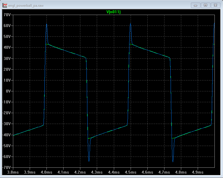
The blue trace is a plot of a tube power amp output with no flyback diodes. The green trace is the same power amp with flyback diodes. Those spikes in the voltage are what can damage a transformer and also what cause "fizz".
In a real tube amp these diodes are under intense stress and may fail. In our virtual world these diodes are indestructible.
So if you like your tones as fizz-free as possible experiment with the Plate Suppressor Diodes parameter. Note that turning them on will reduce the "chime" at edge-of-breakup and may not be suitable for vintage tones.
FRACTAL AUDIO QUOTES
[294] That's what amps do. You don't hear it through a guitar cab typically but using close-mic'd IRs it's more noticeable. You can reduce it by turning on the Plate Suppressor diodes. Trainwrecks have plate suppressor diodes for just this reason.
Power Supply parameters
SUPPLY SAG
From the Owners Manual:
This controls virtual power amp dynamics. Higher settings simulate higher power supply impedance, and thus greater tube plate voltage “droop,” for a more compressed feel. This control interacts with the Master and will have little effect if the power amp is not being “pushed hard”. As Master is increased, the power amp draws more current from its power supply and the Supply Sag control will have more effect.
Sagging softens (squishes) the pick attack, coupled with a swelling rise in volume after the initial drop of the note.
Also read Aiken's White Paper: What is "Sag"?
FRACTAL AUDIO QUOTES
[295] Supply Sag models the power supply resistance. This includes the power transformer, rectifier and any other resistances before the filter caps. The higher the resistance, the more the supply droops when current is pulled from it by the power tubes. The more the supply droops, the spongier the feel.
[296] Supply Sag is the most fundamental of the power supply controls. It controls the virtual resistance of the AC input. In a real tube amp the supply sags due to a combination of power transformer resistance and rectifier resistance. Increasing Supply Sag increases this resistance and vice-versa. The higher the resistance the more the supply sags and the more bouncy and spongey the amp will feel. I like to increase Supply Sag a bit and reduce gain. You can monitor the virtual supply on the hardware by selecting the Supply Sag parameter. The gain reduction meter will display the supply voltage in dB relative to idle.
[297] Sag is also dependent on Master Volume. The higher the MV, the more sag.
High values of Sag along with low B+ Time Constant values can cause “ghost notes” when the supply type is AC (as in a real amp).
Read more about ghost notes in Supply Type
.
FRACTAL AUDIO QUOTES
[298] You can reduce Supply Sag or change the Supply Type to DC to reduce the ghost note. Or increase B+ Time Constant to reduce the supply ripple.
In pre-Cygnus firmware, turning Supply Sag to zero disabled the power amp modeling in the Amp block in the preset. Cygnus firmware has a dedicated switch for this. When the Power Amp Modeling switch is turned off, Master works as a simple volume, and Depth and Presence are deactivated.
FRACTAL AUDIO QUOTES
[299] (Cygnus) With power amp modeling off the Presence control does nothing.
You use Supply Sag to simulate different rectifier types.
FRACTAL AUDIO QUOTES
[300] Reduce to simulate solid-state, increase to simulate tube.
B+ TIME CONSTANT
From the Owners Manual:
This interacts with the Supply Sag control because it makes the virtual power supply response slower or faster. When the supply is fast the amp will sag rapidly accentuating the pick attack and compressing after. Most guitar players like this, but setting it too fast will cause excessive AC ripple and ghost notes. For convenience the virtual power supply voltage (B+) is shown as a meter on this page when the Supply Sag control is selected. (The meter shows dB, relative to the idle voltage.)
High values of Sag along with low B+ Time Constant values can cause “ghost notes” when the supply type is AC (as in a real amp). Lower B+ Time Constant values will make the amp feel “faster” but too low can cause ghost notes.
For convenience the virtual power supply voltage (B+) can be monitored on the PWR DYN tab of the amp block. When the Supply Sag control is selected the gain reduction meter will display the supply voltage in dB relative to the idle voltage.
See Supply Type
to read more about ghost notes.
FRACTAL AUDIO QUOTES
[301] B+ Time Constant is the time constant associated with the Supply Sag parameter. The power tubes draw current from the supply. The supply has a finite resistance. As the power tubes draw more current the supply voltage droops. The rate of change of the droop and recovery is dictated by the supply capacitance. The product of the resistance and capacitance is the time constant. It's typically around 10 ms. You can vary this using the B+ Time Constant parameter.
It is not a simply compression though. As the supply sags, the headroom is reduced but many other things happen. One thing that happens is that the screen voltage droops. The screen voltage is derived from the B+. However the screen has it's own dynamic response, which is often 2nd-order since there is often a filter choke. If you listen carefully to the models with a filter choke you can hear the screen voltage "bounce" when you hit a power chord. The damping of the screen filter is not exposed to the user. When the screen voltage droops, the power tube gain decreases. It effectively shifts the bias point.
There is quiescent draw from the supply as well. As you increase the bias (Power Tube Bias) the quiescent draw increases which decreases available headroom.
The Axe-Fx II does not model all this stuff with compressors, like other products do. It actually uses a differential equation for the supply and the current from the power tubes. It then solves the equation at each sample instant to find the supply voltage and screen voltage.
[302] You can reduce Supply Sag or change the Supply Type to DC to reduce the ghost note. Or increase B+ Time Constant to reduce the supply ripple.
[303] The effect of lower B+ is equivalent to increasing Transformer Match. A lower B+ means the plates clip sooner which is the same as increasing the turns ratio on the transformer. This is assuming that you rebias since typically lower the B+ affects the bias.
[304] The attack comes first as things compress. Then the supply bounces due to a much slower time constant. Compression time constants are in the neighborhood of a few ms, B+ time constants are typically 10-20 ms. You can adjust these on the Advanced page. Many amp designers like a "fast" power supply but if you lower the B+ time constant too much you get ghost notes.
PREVIOUS GENERATIONS
[305] The higher the value the stiffer the power supply. This will result in less compression from the power amp. "Most" guitar players prefer a value around 10ms as it it accentuates the attack without excessive ghosting. It seems as though you prefer less attack so raising the value will accomplish that. Another option is to change the supply type to DC. This will eliminate any ghosting and give you a more "ideal" response. Most modelers use a DC power supply model but I've found that an AC supply model is key to achieving that last few percent of realism. The supply ripple is a big part of why old amps sound the way they do.
Most guitar players actually like a percussive attack so that's why about 10ms has become a de-facto standard.
[306] B+ Time Constant controls the capacitance of the virtual power supply. The more capacitance the "slower" the supply and vice-versa. Most guitar players like a fast supply but too fast will cause excessive AC ripple and create ghost notes (although I think a little ghost note is cool). When the supply is fast it will sag rapidly accentuating the pick attack and compressing after. This parameter works in conjunction with Supply Sag parameter. The time constant remains constant so if you increase Supply Sag the virtual capacitance decreases.
SUPPLY TYPE
From the Owners Manual:
These select between AC and DC virtual power supply types. AC rectification and resulting supply ripple are modeled, and the line frequency is also selectable. Note that as with a real tube amp, the AC Supply can cause “ghost notes” when Supply Sag is low and B+ Time Constant is high. Lower B+ Time Constant values will make the amp feel “faster,” but too low can also cause ghost notes.
This switches between virtual AC (Alternating Current) and DC (Direct Current).
AC LINE FREQUENCY is not the same parameter as AC LINE FREQUENCY in SETUP.
Cliff's Ghost Notes
Tech Note:
A phenomenon present in some vintage amps is an artifact known as "ghost notes".
Ghost notes are the result of intermodulation distortion between the note being played and ripple on the power supply. The ripple is at 120 Hz because the AC voltage is full-wave rectified. So there are frequency components of 120 Hz and its harmonics in the power supply.
These frequency components mix with the note being played and create new tones that are not harmonically related to the note being played. Since it is intermodulation distortion, tones are created at the sum and difference frequencies. For example, if you play a D at the seventh fret on the G string this is 294 Hz. The intermodulation will create new tones at 294 - 120 = 174 Hz and 294 + 120 = 414 Hz. The harmonics of the note being played also factor in. The aforementioned D will also produce tones at multiples of 294 Hz and these mix with the 120 Hz and its harmonics.
The G string above the 5th fret is most prone to this because of the harmonic spectrum of those notes.
The amount of ripple on the supply is a function of the supply impedance. More capacitance and less resistance will reduce the ripple. Conversely less capacitance and/or more resistance will increase the ripple. You can adjust these values in the Axe-Fx using the Supply Sag and B+ Time Constant parameters. Supply Sag adjusts the virtual resistance of the power supply. B+ Time Constant adjusts the resulting time constant of the supply resistance and capacitance, i.e. as you increase the sag the time constant stays constant (capacitance decreases). To counter this increase B+ Time Constant.
Old 100W Plexis exhibit this the most of any amp I've seen due to the high resistance of the power supply transformer. Our reference 100W Plexi has so much power supply resistance that the power supply sags up to 120V! This along with only 50 uF of power supply capacitance leads to prominent ghost notes.
FRACTAL AUDIO QUOTES
[307] The most notable thing would be the ghost notes. There is also a slight difference in feel.
[308] Those old amps make ghost notes. My 100W Plexi has some ghost notes that are louder than the fundamental.
The easiest way to eliminate them (if you don't like/want them) is to simply set the Supply Type to DC.
However, IMO, the ghost notes are a large part of the character of these designs and removing them isn't desirable. Don't over-analyze it. Recognize that certain designs produce ghost notes and embrace it.
[309] Another option is to change the supply type to DC. This will eliminate any ghosting and give you a more "ideal" response. Most modelers use a DC power supply model but I've found that an AC supply model is key to achieving that last few percent of realism. The supply ripple is a big part of why old amps sound the way they do.
Most guitar players actually like a percussive attack so that's why about 10ms has become a de-facto standard.
[310] 100 watters are usually worse because they have lighter filtering (50 uF vs. 100 uF) and draw more dynamic current.
[311] One of the reason amps in Europe sound different than US.
[312] So I was testing the next beta and selected the AC-20. Was hearing a lot of ghost notes compared to the old algorithm (in the debug build I can select between algorithms with a hidden parameter) and figured that couldn't be right. Hooked up the real AC-20 and, sure enough, ghost notes galore at the same settings.
[313] If you don't want authentic ghost notes set the Supply Type to DC.
[314]
Ghost notes are intermodulation distortion between the power supply ripple and the audio. There are several ways to reduce it:
- Change the supply to DC. This will completely eliminate it as there will be no supply ripple.
- Reduce the supply sag. This will reduce the amount of ripple but also reduce the power amp compression due to supply sag.
- Increase the B+ time constant. This will also reduce the amount of ripple but slow the response of the supply.
Ghost notes are intermodulation products between the power supply and the note being played. Plexis often demonstrate this due to their fast power supplies (which yields more ripple). They're not harmonically related to the note being played. Some people find them undesirable, others find they add "complexity". Usually most audible on the G string in the middle of the fretboard. Many products do not accurately reproduce them or reproduce them at all.
[315] Intermodulation is different than "ghost notes". IM occurs whenever two sine waves are passed through a nonlinearity (i.e. distortion). The nonlinearity causes the sum and difference of the input frequencies and their harmonics. The human ear is slightly nonlinear so we hear a "beat" when playing two notes together. Put these two notes through distortion and the beat frequencies are amplified greatly. Some RF circuits actually exploit IM as a method of demodulation. The RF input and a carrier are applied to a nonlinearity. The difference frequency is the desired baseband signal. This is mostly done at microwave frequencies where conventional mixing techniques aren't viable. Ghost notes are a form of amplitude modulation . The cause of ghost notes is excessive AC ripple on the B+. The ripple modulates the gain of the output stage. Ghost notes are especially undesirable because they are harmonically unrelated and occur even when playing single notes. The cure is improved power supply and/or screen grid filtering. Some modelers model ghost notes. It is the opinion of this designer that any amp exhibiting ghost notes is poorly designed and/or needing repair and hence I don't model them.
[316] The AC power supply is modeled and any hum and ghost notes in the power amp will be reproduced. What is not reproduced is hum due to AC heaters, thermal noise, and other sources of interference. These are considered objectionable.
[317] You can reduce Supply Sag or change the Supply Type to DC to reduce the ghost note. Or increase B+ Time Constant to reduce the supply ripple.
[318] It actually IS intermodulation distortion but it's intermodulation between the note your playing and the power supply ripple. You can also change the "flavor" a bit by altering the AC Line Freq. An amp in Europe will sound different because the line frequency is 50 Hz.
PREVIOUS GENERATIONS
Firmware release notes - Axe-Fx II:
Amp block power supply modeling now models AC rectification and resulting supply ripple (if Pwr Supply Type is set to ‘AC’). The power supply type can be selected between AC and DC with the Pwr Supply Type parameter. The line frequency can be selected with the AC Line Freq parameter. Note that high values of Sag along with low B+ Time Constant values can cause “ghost notes” when the supply type is AC (as in a real amp). Lower B+ Time Constant values will make the amp feel “faster” but too low can cause ghost notes.
AC LINE FREQUENCY
See Supply Type
for more information.
VARIAC
From the Owners Manual:
This sets the relative AC line voltage into the amp simulation. Volume varies greatly when a Variac is used with a real amp, but the virtual variac compensates for this.
A Variac is said to be required to achieve VH's "Brown" sound. Try it at 75% with a Plexi.
FRACTAL AUDIO QUOTES
[319] The Spongy/Bold switch (on a Mesa) is basically a Variac.
[320] It's impossible to compensate exactly. Some manual adjustment of the volume may still be required.
[321] The whole amp voltage is reduced.
The variac changes the line voltage by the percentage selected.
SCREEN FREQUENCY + SCREEN Q
From the Owners Manual:
These set the resonant frequency of the virtual power tubes’ screen filter, and the Q of that filter.
Speaker parameters
The parameters on this page shape the virtual speaker impedance curve and the resulting resonances in the virtual power amp. Amp and speaker interaction affects tone by causing an increase in power amp response at certain frequencies. Note that setting Negative Feedback greater than “0” flattens the effect of the response curve.
LOW FREQUENCY RESONANCE
From the Owners Manual:
Guitar loudspeakers have strong low-frequency resonance. This shifts up slightly when the speaker is mounted in an enclosure. This resonance causes an increase in the power amplifier response due to the finite output impedance of the power amp.
The default LF and HF Resonance settings in an amp model are based on the selected Speaker Impedance Curve in the Amp block.
Setting the Speaker Impedance Curve to "Resistive Load" is identical to turning off LF Resonance and HF Resonance. [322]
When using a solid-state power amp with a traditional guitar cab, finetuning LFR can get you better results.
Cliff's About Matching Your Cabinet's Resonant Frequency
Tech Note:
This post is aimed at those who use a solid-state power amp into a conventional guitar cab.
As is described in the post "About Speaker LF Resonance" a guitar cabinet has an impedance resonance in the low frequencies. This typically falls in the range of 50 to 100 Hz.
A tube amp, being essentially a current source, will have a voltage output that follows the impedance curve. Speakers, being electromotive devices, respond to applied electromotive force (EMF) which we know as voltage.
A solid-state power amp is a voltage amplifier and, hence, will not be influenced by the impedance of the speaker.
When using a solid-state power amp into a conventional guitar cabinet the experience will be different if the simulated speaker in the Axe-Fx II is not adjusted to match the actual speaker. Whether or not this is important is up to the individual but I imagine a lot of the posts about "in-the-room using power amp and cab is not the same" are due to this. Unfortunately the Axe-Fx II cannot measure the speaker impedance characteristics as it is not directly connected to the speaker. No device can measure the speaker impedance without being directly connected to the speaker, despite what their marketing claims may infer (cough, ahem...), since impedance is, by definition, V/I and we cannot measure these unless connected to the speaker terminals.
The only truly accurate way to set the simulated speaker is to measure the speaker being used with an impedance measuring device. These can be had relatively inexpensively in the form of the Woofer Tester 3 (from Dayton Audio IIRC). You can also make your own using a small value resistor (0.1 ohms or so) in series with you power amp and measure the voltage across the resistor.
The next best method would be to estimate the impedance using published data from the speaker manufacturer. If the make and model are known the data may be available. Add approximately 10% to the published resonance frequency if the speaker is in a sealed box.
The worst method, and the subject of some contention, is finding the resonance by "feel". No power amp has perfect damping. If you put a sine wave (use the Synth block) into the speaker you may be able to observe or feel the resonant frequency. The cone will have increased excursion at this frequency. Of course you may just be feeling the room resonance. I have used this technique successfully on several speakers but it takes practice. The main drawback is that the magnitude of the resonance is unknown.
The Axe-Fx II's Low Res parameter is displayed in dimensionless units from 0 to 10. Each unit corresponds to 2.4 dB of impedance "gain". We define this as a gain since the our current source power amp will experience a voltage gain. This is relative to the DC resistance of the speaker. For example, if the speaker's resistance is 6 ohms and the impedance at resonance is 60 ohms then our impedance gain would be 20*log10(60/6) = 20 dB. Dividing by 2.4 gives a Low Res value of 8.3. Since a tube amp isn't a perfect current source these values should be reduced slightly. The exact value of the Q isn't too important. About 2.0 is a good starting point. Adjust up or down to taste. If you are anal more information is in the aforementioned post about deriving the value of Q.
Once the simulated speaker is set correctly you may notice a difference in low-frequency behavior and pick attack.
Cliff's About Speaker LF Resonance
Tech Note:
Most guitar speakers are roughly the same when it comes to the high-frequency reactive behavior. The impedance increases starting around 1 kHz and then increases at 3-4 dB/octave. This is due to the voice coil inductance. A pure inductance would increase at 6 dB/oct. but there are eddy current losses that make the voice coil look "semi-inductive". The Axe-Fx II models this with a high-order lossy inductor model.
The low-frequency response of guitar speakers, however, varies greatly between speakers of different makes and models. This low-frequency response is a sharp resonance typically in the range of 50-150 Hz. The magnitude of this resonance varies from several to 20 times the nominal impedance.
The impedance of a speaker influences the response of a tube amp since a tube power amp is essentially a transconductance amplifier. It creates a current for an applied voltage. This current in turn creates a voltage across the speaker terminals that is dependent upon the impedance of the speaker. Therefore the power amp will resonate at the resonant frequency of the speaker. This causes certain notes to become emphasized as they excite the resonant frequency. Negative feedback around the power amp will reduce the amount of resonance but not all amps use negative feedback (i.e. Vox).
The increased voltage amplitude at the resonant frequency also causes the power amp to clip sooner at the resonant frequency. Think of it this way: if the power tubes are swinging, say, 200 V at the midrange frequencies, they will swing X times more at the resonant frequency where X is the ratio of the resonant impedance to the nominal impedance. So if the resonant impedance is 10 times the nominal impedance the power tubes will want to swing 2000 volts. This is impossible so they will clip. For high-gain tones this can cause the tone to sound muddy or feel spongy. For lower gain tones this can thicken the tone and make it feel, well, more spongy.
Cabinet/speaker IR data does not contain the impedance information. The only way to obtain impedance data is to measure the current vs. voltage vs. frequency (despite what modeler advertising literature would like you to think).
The Axe-Fx uses default values of LF Resonant frequency and impedance for each amp model. For models based on combo amps these values are derived from measurements of the actual amp's speaker. For models based on amp heads the values are based on measurements of the cabinet most likely to be used with that head.
You can adjust the frequency and impedance to suit your taste. Reducing the impedance (Low Res) will reduce the bass response and can give tighter bass. Raising the impedance will increase the bass response and can give a fuller sound. Altering the frequency (Low Freq) will change the frequencies at which the power amp resonates and tuning this to the key you are playing in can be an effective strategy, e.g. set it to 82 Hz if playing in E.
Don't be afraid to try drastic settings. Try turning Low Res all the way to zero. Compensate by adding some bass with the Bass knob or the EQ section. As I mentioned earlier the LF Resonance will cause the power amp to clip earlier than it will when amplifying midrange frequencies. Turning down the Master Volume will increase the headroom in the power amp and reduce this clipping. Furthermore the Transformer Match also influences when the power amp clips. So there is a relationship between LF Res, MV and Transformer Match.
Many manufacturers publish impedance data for their speakers. Eminence and Jensen and probably others publish detailed impedance data. You can look at the impedance plots and set the resonance parameters to match (roughly). The Low Res parameter is indicated from 0 to 10 and sets the resonance in dB from 0 to 24 dB (dB is a ratio of powers so it's not really the proper units for this but that's semantics). For example, the Jensen P12N has resonant frequency of about 100 Hz so you would set Low Freq to 100 Hz. The impedance at this frequency is about 40 ohms. To get the Low Res amount use the formula (20 * log10(Zr/Rdc)) / 2.4 where Zr is the impedance at the resonant frequency and Rdc is the DC resistance. For this speaker Low Res is then (20 * log10(40/6.2)) / 2.4 = 6.7.
A power amp isn't perfect though. Winding resistance in the output transformer increases Rdc, typically by a couple ohms. Therefore our above example would become (20 * log10(40/8.2)) / 2.4 = 5.7. The exact value isn't overly critical though and all this is subtle nuances.
The resonance Q is a bit more difficult to calculate. It is derived from the bandwidth at the points where the impedance "gain" is the square root of the resonance impedance gain. IOW, if the impedance is, say, 10 times the nominal impedance then the bandwidth is given by the frequencies where the response is 3.16 times the nominal impedance. For our example the resonance gain is 5 (40 / 8 = 5). So the bandwidth is the frequencies at which the impedance equals sqrt(5) * 8 = 18. From the graph this is approximately 75 Hz and 130 Hz. Q is defined as f0 / bw so our resulting Q is 100/60 = 1.67. Most speakers have a Q of around 2.0 or so. Again the exact value isn't overly critical and don't be afraid to try extreme settings (you can't break anything).
Finally, just because real speakers behave like this doesn't mean we have to adhere to this behavior. Perhaps a better speaker has no resonance (Low and High Res are zero), or maybe the Q is a lot lower or higher. In our virtual world we can design a speaker that is impossible to construct in the physical universe.
tl;dr version: Mess with Low Freq and Res if you want, or not.
FRACTAL AUDIO QUOTES
[323] The speaker tab is not an EQ. It allows you to adjust the impedance that the virtual speaker presents to the virtual power tubes. In most cases the resulting EQ is quite different than the impedance curve since negative feedback flattens the response. If you turn the damping all the way down then the EQ will be close to the impedance curve (but still influenced by the transformer).
[324] The resonant frequency goes up when mounted in a cabinet. It doesn't need to be spot-on. If you are within 10% you'll be fine.
If you want to be anal about it you can use an impedance analyzer. This is what we use: Dayton Audio DATS Dayton Audio Test System 390-806.
[325] The speaker page is the impedance vs. frequency. For a guitar amp with no negative feedback the voltage frequency response of the power amp will very closely match this since the power amp is basically a current source (V = I * Z). There will a slight reduction in the peaks as the output impedance isn't infinite but it is very high and will therefore be very close.
Regarding LF:
[326] […] In general the Q is between 2 and 2.5 […]The Hi Freq is usually between 1 and 1.5 kHz. Hi Freq sets the critical frequency (or corner frequency) of the inductive portion of the loudspeaker's response. The critical frequency is the frequency at which the reactive component of the impedance is equal to the resistive component. This is found by fc = R/(2*pi*L). For a typical speaker R is around 6 ohms and L is around 0.75 mH. Therefore fc = 1270. Jensens tend to have higher inductance so that would move this value down. Eminence speakers tend to have lower inductance so that would move this value up. Celestion does not publish their values so I used Eminence values when calculating the defaults. You'll notice the Marshally stuff has fc around 1500 which is consistent with a typical Eminence copy of a Greenback.
[327] You cannot obtain speaker impedance via audio stimulus and microphone measurement. Impedance is defined as voltage divided by current so you need to measure the current vs. applied voltage across the frequency range of interest.
I have the equipment to do it, and have measured many speakers, but the average person doesn't have the equipment nor the knowledge to use the data.
The influence of speaker impedance is generally not that great. The exception are amps with no negative feedback. In these cases the speaker impedance has a much more pronounced effect on the overall response. These amps include Vox, Matchless and most other "Class-A" designs. As soon as you add negative feedback the response flattens considerably. However... Presence and Depth reduce negative feedback so if you dial significant amounts of those in then the speaker impedance becomes a factor again.
All-in-all you only have to be in the ballpark. 1500 Hz is a good starting point for Hi Freq. Adjust up or down slightly by ear. I don't believe that 3000 Hz is accurate. I've never seen a speaker that would have the corner frequency that far out.
[328] [...]As I explained a few posts up I wouldn't set Hi Freq outside the range of 1.0 to 1.6 kHz. Vibroverb model is an exception (800 Hz) since it had a more voice coil inductance.
[329] I call it critical frequency since it is similar to the critical or corner frequency of a filter. I had to come up with some way of setting the loudspeaker inductance relative to the resistance. Frequency seemed to make more sense. I thought about an inductance parameter but figured that would be too nebulous. At the default settings the impedance rise of the simulated voice coil matches very close with published data. I have overlaid the modeled impedance curve with published data and it is a very good fit.
For example, take the JCM800 model. The graph on the SPKR page has a scale of +20 dB at the top. Look at the response at 2kHz. It's roughly 1/4 of full-scale which equates to 5 dB. If we look at the impedance curve for a typical 8-ohm speaker we see that the impedance at 2 kHz is roughly 13 ohms. For a 6.5 ohm voice coil (typical) this means that the voltage at the speaker is 6 dB higher at 2 kHz. Pretty darn close to what the graph is showing.
While there is no high-frequency resonance in the speaker itself, a resonance IS formed due to the winding capacitance of the transformer. This capacitance resonates with the voice-coil inductance.
[330] The negative feedback is set in the Advanced menu. The SPKR page only sets the impedance curve of the speaker/OT combo.
The values chosen are prototypical for the speaker used with the modeled amp.
You should not need to vary these parameters much IMO. I only ever vary Low Freq and High Freq. Whenever I'm matching an amp I adjust Low Freq to match the resonance of my reference cabinet. I occasionally vary Hi Freq to get more or less midrange bite.
[331] Negative feedback does not affect the speaker impedance. Speaker impedance is an independent variable. The default values are based on the speaker cabinet most commonly used with the amp. In the case of a combo it's the internal speaker. For heads it's the mating cabinet, if one.
A typical speaker has a low-frequency resonance with some frequency, Q and magnitude. The Q is typically around 2, frequency around 100 and magnitude around 12 dB. These values are dependent upon the speaker construction and, to a lesser extent, the cabinet.
The voice coil inductance causes the impedance to increase at high frequencies. Unlike a pure inductance which would increase at 6 dB/octave, voice coil inductance is semi-inductive and typically increases at 3-4 dB/octave. The "break" frequency is dependent upon the actual inductance and is adjustable.
The Axe-Fx is unique in that it lets you adjust these values. Most products just use a fixed curve.
[332] The voltage at the output of a tube amp is a function of the speaker's impedance curve. The impedance curve is set in the SPKR tab of the amp block.
Real speakers respond to the VOLTAGE at their terminals, not the current. The amp block creates a virtual voltage which is a function of the amp model and the impedance curve.
The cab block uses IRs which represent the measured sound from the speaker vs. an applied voltage at the speaker terminals. The aforementioned virtual voltage is sent to the cab block which then produces an audio signal by convolving the virtual voltage data with the IR.
As I said in my previous post the IR is largely independent of it's impedance curve. The impedance curve can then be seen as just another tone and feel shaping tool. Bass too prominent? Turn down LF Resonance. Want more midrange? Lower HF Res Freq. The degree to which the impedance curve affects the output of the amp block is a function of the power tube type and the amount of negative feedback. The less negative feedback the more the impedance curve influences the output. Since Presence and Depth work by reducing negative feedback at high and low frequencies respectively, increasing them will also increase the influence of the impedance curve at those frequencies. The dynamic impedance of the power tubes also affects the output. A power triode, for example, has a much lower plate impedance than a tetrode or pentode and, therefore, the output will be mostly independent of the speaker impedance.
[333] The speaker resonance is NOT proportional to the master volume level in the real world. The speaker impedance curve does change under drive level (at the speaker terminals) and that is modeled but the amount of change is very small.
[...]
The Axe-Fx III is extremely accurate in its modeling, especially the power amp modeling as that is where much of the magic happens. This has been proven time and time again in controlled studies. We compare the models to the amps at levels from barely audible to ear bleeding using measurement equipment as well as listening tests and blind A/B evaluations.
[...]
In a loudspeaker the resonances do change a bit vs. applied voltage but the effect is subtle. The Axe-Fx III models this (it's the Speaker Compliance parameter). For all intents and purposes though it's pretty much a static network as the parameter shift only occurs at large excursion values which only occur at very low frequencies (excursion is the integral of applied voltage).
[334] There are certain aspects that simply can't be modeled and require user intervention. For example, a speaker has a low-frequency resonance. A tube amp will create a higher output at that resonant frequency. The Axe-Fx has no way of knowing what that resonant frequency is and defaults to a value that is common for the speakers that are typically used with that amp. However, if you drive that speaker through a solid-state amp you won't excite the resonance unless you adjust the Speaker Resonant Frequency to match it.
[335] One way to find the SRF is to put a Filter block after the amp block. Set the type to Peaking, Q to 5 or so and Gain to 10 dB. Start with a Freq. of 50 Hz. Play some chugga-chugga and slowly adjust the Freq. until you hear and feel the cabinet resonate. Make a note of the frequency. Remove the filter block and set the amp block SRF to match. 4x12s typically have an SRF of between 80 and 120. Open back cabs are typically a bit lower.
[336] (Once I know what frequency to pick for my cab, and roughly which amount and Q to use, is it ok and expected to use the same settings for every amp model?) Yes, keep the same settings for all models.
HIGH FREQUENCY RESONANCE
See Low Frequency Resonance
above for more information.
From the Owners Manual:
A loudspeaker voice-coil presents an inductive load to the power amp at high frequencies. This inductive load, in conjunction with the output transformer capacitance, creates a high-frequency resonance at the specified frequency.
High Frequency Slope allows fine adjustment of the high-frequency impedance of the virtual voice coil (which affects the slope of the impedance curve). A speaker voice coil is “semi-inductive” due to eddy current losses in the motor. This presents an impedance to the power amp that is neither fully inductive nor fully resistive. The amount of resistive loss varies by brand and type. Reducing Slope simulates a speaker that is less inductive, increasing Slope simulates a speaker that is more inductive. Typical speakers range from 3.0 to 4.5 with the median being about 3.7. Lower values yield greater midrange while higher values are more scooped and sizzly.
Cliff's About HF Resonance
Tech note:
In the SPKR page of the Amp block are various parameters. I've talked about low-frequency resonance in another post. In this post I will address high-frequency resonance.
As with LF resonance the high output impedance of a tube power amp causes the frequency response to follow the impedance of the speaker. There are two primary components: LF resonance and a high-frequency boost. The HF boost is due to the inductance of the voice coil.
At the frequency where the voice coil reactance is equal to its resistance the impedance will start to rise. If this were a "pure" inductance it would rise at 6 dB per octave. However eddy-current losses in the motor cause this inductance to be "semi-inductive" and the impedance typically rises between 3 and 4 dB per octave. Different brands and models of speakers behave differently. You can look at the spec sheet for a speaker to get an idea as to the behavior of the speaker. The formula for the break frequency is given by f = R / (2*pi*L). For example, if the voice coil inductance is 1 mH and the resistance is 7 ohms then the break frequency would be 7/(6.28*0.001) = 1.1 kHz.
The Axe-Fx II allows you to adjust the virtual voice coil via the HI FREQ and HI RES parameters. The HI FREQ parameter sets the "break" frequency which is the frequency where the inductive reactance equals the voice coil resistance. For most speakers it is around 1000 Hz. It is lower for larger speakers and higher for smaller speakers usually. The HI RES parameter sets the rate at which the impedance increases. The default value of 5.83 is around 3.5 dB per octave.
If you want a smoother sound you can increase HI FREQ and/or decrease HI RES. If you want more highs or "chime" you can decrease HI FREQ and/or increase HI RES. Experiment with different values to get a feel for the response.
Note that the amount of feedback (Damping parameter) will influence the behavior of these controls. With no feedback (Damping = 0) the frequency response follows the impedance curve virtually 1-for-1. As Damping is increased the frequency response flattens and the impedance curve has less influence on the response.
As with all things in the Axe-Fx, use your ears.
FRACTAL AUDIO QUOTES
[337] The HF Resonance Frequency is the "corner frequency" of the voice coil inductance. As this inductance isn't a pure inductance due to eddy currents the calculation is a bit complex however it is roughly equal to:
fc = R / (2 * PI * L)
where R is the voice coil resistance and L is the inductance.A typical voice coil has R = 7 and L = 1 mH. This yields:
fc = 7 / 6.28e-3 = 1100 Hz.Most voice coils are a bit lower inductance than this. The typical range for fc is 1200 - 1500 Hz.
PREVIOUS GENERATIONS
[338] Regarding LF:
In general the Q is between 2 and 2.5.The Hi Freq is usually between 1 and 1.5 kHz. Hi Freq sets the critical frequency (or corner frequency) of the inductive portion of the loudspeaker's response. The critical frequency is the frequency at which the reactive component of the impedance is equal to the resistive component. This is found by fc = R/(2*pi*L). For a typical speaker R is around 6 ohms and L is around 0.75 mH. Therefore fc = 1270. Jensens tend to have higher inductance so that would move this value down. Eminence speakers tend to have lower inductance so that would move this value up. Celestion does not publish their values so I used Eminence values when calculating the defaults. You'll notice the Marshally stuff has fc around 1500 which is consistent with a typical Eminence copy of a Greenback.
[339] You cannot obtain speaker impedance via audio stimulus and microphone measurement. Impedance is defined as voltage divided by current so you need to measure the current vs. applied voltage across the frequency range of interest.
I have the equipment to do it, and have measured many speakers, but the average person doesn't have the equipment nor the knowledge to use the data.
The influence of speaker impedance is generally not that great. The exception are amps with no negative feedback. In these cases the speaker impedance has a much more pronounced effect on the overall response. These amps include Vox, Matchless and most other "Class-A" designs. As soon as you add negative feedback the response flattens considerably. However... Presence and Depth reduce negative feedback so if you dial significant amounts of those in then the speaker impedance becomes a factor again.
All-in-all you only have to be in the ballpark. 1500 Hz is a good starting point for Hi Freq. Adjust up or down slightly by ear. I don't believe that 3000 Hz is accurate. I've never seen a speaker that would have the corner frequency that far out.
[340] [...] As I explained a few posts up I wouldn't set Hi Freq outside the range of 1.0 to 1.6 kHz. Vibroverb model is an exception (800 Hz) since it had a more voice coil inductance.
[341] I call it critical frequency since it is similar to the critical or corner frequency of a filter. I had to come up with some way of setting the loudspeaker inductance relative to the resistance. Frequency seemed to make more sense. I thought about an inductance parameter but figured that would be too nebulous. At the default settings the impedance rise of the simulated voice coil matches very close with published data. I have overlaid the modeled impedance curve with published data and it is a very good fit.
For example, take the JCM800 model. The graph on the SPKR page has a scale of +20 dB at the top. Look at the response at 2kHz. It's roughly 1/4 of full-scale which equates to 5 dB. If we look at the impedance curve for a typical 8-ohm speaker we see that the impedance at 2 kHz is roughly 13 ohms. For a 6.5 ohm voice coil (typical) this means that the voltage at the speaker is 6 dB higher at 2 kHz. Pretty darn close to what the graph is showing.
While there is no high-frequency resonance in the speaker itself, a resonance IS formed due to the winding capacitance of the transformer. This capacitance resonates with the voice-coil inductance.
[342] The negative feedback is set in the Advanced menu. The SPKR page only sets the impedance curve of the speaker/OT combo.
The values chosen are prototypical for the speaker used with the modeled amp.
You should not need to vary these parameters much IMO. I only ever vary Low Freq and High Freq. Whenever I'm matching an amp I adjust Low Freq to match the resonance of my reference cabinet. I occasionally vary Hi Freq to get more or less midrange bite.
TRANSFORMER LOW/HIGH FREQUENCY (XFORMER LF/HF)
From the Owners Manual:
These set the output transformer bandwidth.
The Transformer LF parameter effectively adjusts the transformer’s inductance. Increase this value to simulate a smaller transformer, decrease to simulate a larger transformer.
Transformer is sometimes abbreviated to: XFRMR.
FRACTAL AUDIO QUOTES
[343] XFRMR LF sets the low frequency -3dB point of the output transformer. Most transformers actually have a very low -3dB point (contrary to internet wisdom) however their full-power -3dB point is significantly higher. The Xfrmr Drive control sets the full-power -3dB point.
SPEAKER IMPEDANCE CURVE
From the Owners Manual:
Tucked away near the end of the advanced menu is this remarkable little parameter. It selects between 50+ high-order speaker impedance modeling curves. Changing the amp Type will load an appropriate curve automatically. The Cabinet Resonance parameter can be used to adjust the amount of cabinet resonance in the impedance curve, an effect made instantly more visible on the graph shown on the “Speaker” page of the amp block edit menu and in Axe-Edit III or FM3-Edit.
Firmware Ares 11 for the Axe-Fx III:
Amp block now uses new high-order speaker impedance modeling. 52 speaker impedance models (and two LB-2 models) are included and can be selected using the Speaker Impedance Curve parameter (on the Advanced page). Selecting an amp model will load an appropriate default Speaker Impedance Curve for that amp model. The Cabinet Resonance parameter can be used to adjust the amount of cabinet resonance in the impedance curve.
The Speaker Impedance Curve parameter is often abbreviated to SIC. It sets the desired impedance curve for the selected amp model. Together with the selected cab model (IR) in the Cab block, this parameter mainly affects feel
and bass response. It has a large impact.
You can choose from many provided curves. You can either choose a curve that authentically fits the selected cab model (IR), or another one that sounds and feels great.
Setting the SIC to Resistive Load
is identical to turning off LF Resonance and HF Resonance. [344]
The parameter Cabinet Resonance on the Speaker page of the Amp block lets you set the desired amount of cabinet resonance in the curve (default: 100%).
FRACTAL AUDIO QUOTES
[345] Firmware 11.0 introduces our new high-order speaker impedance modeling. We've curated the impedance data from nearly 50 cabinets. You'll now be able to select the impedance curve to use with an amp model (selecting an amp model loads the most appropriate curve for that model).
Why is this important? When you look at speaker impedance curves they look pretty simple. However that data is obtained when the speaker is mounted on an infinite baffle. As soon as you mount the speaker in a cabinet that impedance data changes, sometimes quite radically. The modes of the cabinet introduce significant peaks and dips in the impedance due to the back EMF created. Some of the cabs we measured have deviations from the published curves by 4-5 dB or more.
To understand why this happens the impedance of a speaker is dependent upon the acoustic load. In an infinite baffle the load is constant. Put the speaker in a box and the load is greater at some frequencies and lower at others because the sound waves bounce off the walls and constructively or destructively interfere with the motion of the speaker. For example, consider the sound emanating from the speaker and bouncing off the back wall of the cabinet. When the sound wave reaches the speaker it will either aid or oppose the motion of the speaker. If it aids the motion then the impedance will be lower and vice-versa.
[346] The impedance has a nonlinear component but it is very small relative to the linear component. IOW the amplitude of the wave is proportional to speaker displacement so the impedance curve is relatively constant vs. applied voltage. The nonlinear effects occur as the voice coil moves out of the magnetic gap and this is already modeled.
[347] A tube power amp is a transconductance amplifier, voltage in - current out. A speaker is a voltage transducer, voltage in - sound out. Since the power amp is driving current the voltage at the speaker is the current times the impedance of the speaker (Ohms law V = I*R). The voltage therefore is dependent upon the impedance.
A solid-state power amp is a voltage amplifier, voltage in - voltage out. Since the power amp is driving voltage the voltage at the speaker is NOT dependent on the impedance of the speaker.
When an IR is captured (correctly) it is done using a solid-state power amplifier so the effects of impedance do not influence the measurement. Some people try to use tube power amps to capture IRs. This is incorrect methodology.
The Axe-Fx power amp simulation is a transconductance simulation. It uses a simulated speaker impedance to derive the output voltage that then drives the simulated cabinet (IR).
Firmware 11.xx has 47 (and counting) speaker impedance curves that you can select that allow for different power amp transconductance responses. Moreover the impedance simulation is now a high-order network that simulates the perturbations in impedance due to cabinet resonance.
If you are using a conventional guitar cab and solid-state power amp ideally you would want to know the impedance curve of the cabinet. This requires special test equipment although I'm working on a idea to use the outputs of the Axe-Fx directly along with a special cable to allow field measurements by users. At this time the impedance curve matching is a Matlab program though and requires some hand-tuning.
[348] The graph shown is the resulting response of the SIC plus the response of the transformer.
[349] Choose an impedance curve that most closely matches the speaker you used.
[350] The Null curve simulates a purely resistive load. No real speaker exhibits this type of impedance curve. It's simply there for reference.
[351] The little spikes are due to reflections, both internal to the cabinet and external from the room. The sound bounces off things and when it arrives in phase or out of phase with the speaker it changes the impedance.
Noise in the environment can also impact the measurement. Ideally the environment should be as quiet as possible.
[352] Air is very linear.
The impedance curve changes, but not for those reasons. It changes because the amount of voice coil in the magnet gap changes as the speaker moves. When the speaker moves one way more windings are in the gap and vice-versa. This changes the effective voice coil inductance.
Also, the low frequency resonance changes (slightly) as a function of displacement. This is due to the compliance of the suspension changing with displacement. Compliance also changes due to a change in Force Factor (B*l) which is a function of displacement.
There are no nonlinear effects due to "chunking at higher volumes". The cab does not have "resistance".
FWIW, the impedance curves in the Axe-Fx are not static. They are dynamic. You can vary the amount of impedance shift using the Speaker Compliance parameter.
[353] The response of a tube amp is dependent upon the speaker impedance. If you use a speaker with same impedance curve as the model then the response of the model will be very close to the real amp (component tolerances are still a factor). If your speaker's impedance curve is different then there will be audible differences.
In the Amp block you can select different impedance curves. Switch through them and notice the difference in response, particularly in the bass.
Our modeling is extremely accurate but matching a particular copy of an amp is limited to variables beyond our control like speaker impedance curve, component tolerances and design changes. [...]
[354] Amps with low amounts of negative feedback in the bass region are sensitive to the impedance curve. The 5153 is one of these amps due to its NFB circuit.
[355] The impedance curve MUST be in the amp block. A power tube is essentially a curren source. So the output voltage of a tube amp is the current times the impedance. If the power amp is driven hard (and it usually is because that's where it sounds best) then the voltage will eventually clip. The lows and highs clip first because the impedance curve is sort of a bathtub shape. If the impedance curve is not in the amp block then the power amp cannot clip correctly. Negative feedback essentially flattens the impedance curve. So if the impedance curve isn't part of the amp block there's no way to flatten the curve depending upon the amp's negative impedance. The negative feedback is often shaped, i.e. Presence/Depth controls. The amount of signal fed back, however, is dependent upon the impedance curve because the output voltage is a function of the impedance curve. This results in a complex interaction between the impedance curve and the Presence/Depth controls. The power drawn from the power supply is a function of the impedance curve. The low frequencies and high frequencies clip earlier than the midrange so the midrange draws more power which results in more compression in the midrange. It's simply wrong to apply the impedance curve anywhere but in the amp block. Applying some generic impedance curve to IRs is crude and nowhere near to what a real amp does.
[356] In a tube power amp the lows and highs distort first because they are boosted by the speaker impedance. This causes the sound to become more midrangey and focused. Then as the signal decays the sound becomes fuller and less midrangey. It's literally one of the most important things in the way a tube amp operates and is responsible for its unique and pleasing overdrive behavior and why they became the gold-standard. This is also what makes an AC30 so unique. AC30s have no negative feedback so the lows and highs are fully boosted by the speaker impedance. When you drive them hard they get focused. When you back off the volume the become full and chimey.
[357] Speaker impedance varies with motor temperature and cone displacement. We model both. The speaker impedance curve represents the impedance with the speaker at rest.
Leon Todd's video explains this feature.
The Amp block in presets prior to firmware Ares 11 also relied on an impedance curve. A parameter in SETUP on the Axe-Fx III, FM3 and FM9 lets you decide to keep using the old values or update the preset to the newer specs. Then, when loading such a preset, the device either automatically selects the most fitting speaker impedance curve (you need to save the preset to make it permanent), or sticks with the pre-11
impedance/resonance curve.
From the Owners Manual:
Setting Global "Update Pre-11.x Presets Spkr Imp Upon Load" parameter to YES will automatically update the Speaker Impedance Curve for the Amp blocks upon preset recall to use an appropriate Speaker Impedance Curve for that amp model. Setting the parameter to NO will leave existing presets unaffected. NOTE: Setting this to YES will also cause the EDITED LED to light indicating the preset has been modified.
Firmware 18 for the Axe-Fx III added the Speaker Impedance Curve parameter to SETUP. When set to DEFAULT the speaker impedance curve used when selecting an amp model is the default curve for that amp model, otherwise it is the selected curve. NOTE: this does not affect existing presets. The selected curve is used only when selecting a new amp model.
Firmware 22 and later for the Axe-Fx III enable automatic adjustment of the Speaker Impedance Curve in the Amp block when selecting Dyna-Cab
in the Cab block:
The Amp block now features “Auto Dyna-Cab Impedance”. When set to ON the speaker impedance curve of the Amp block will follow the Cabinet Type in the first mixer slot of the associated Cabinet block. I.e., if the Cab Type in the first mixer slot of Cabinet 1 is, say, 4x12 5153 and the Mode is Dyna- Cab then Amp 1’s speaker impedance will automatically be set to 4x12 5153.
FRACTAL AUDIO QUOTES
[358] All Dyna-Cabs have corresponding impedance curves that were taken from the actual cabs.
SPEAKER IMPEDANCE CURVES LIST
The current speaker impedance curves in the Amp block are listed below. The details are based on available information about the amps and cabs in Fractal Audio's possession.
- 1x8 5F1 Tweed — Fender Champ combo with 8" speaker. DynaCab: 1x8 5F1 Tweed.
- 1x8 Princetone — 5F2 Tweed Princeton with a "very nice sounding" 8” Jupiter speaker.
- 1x10 BF Princetone — blackface Fender Princeton Reverb combo with 10" speaker. DynaCab: 1x10 BF Princetone
- 1x10 Metro Blues — MESA Subway Blues combo with 10" Eminence Black Shadow. DynaCab: 1x10 Metro Blues
- 1x10 Princetone NR — 1959 5F2-A Fender Tweed Princeton combo with 10" speaker.
- 1x10 SF Princetone — silverface Fender Princeton combo with 10" speaker. DynaCab: 1x10 SF Princetone
- 1x12 AC-20 DLX — Morgan AC20 Deluxe combo with 12" G12M75. DynaCab: 1x12 AC20
- 1x12 AST BV25 — Swart Atomic Space Tone with 12" Mojotone BV-25m. DynaCab: 1x12 Nuclear Tone
- 1x12 Black Magick — Supro Black Magick with 12" Jensen P12Q speaker.
- 1x12 Brit G12H55 — 1x12 cabinet with 12" Celestion G12H, low (bass) resonance (55 Hz).
- 1x12 Brit G12H75 — 1x12 cabinet with 12" Celestion G12H, high resonance (75 Hz).
- 1x12 1x12 Div13 CJ11 — Div13 CJ11 combo with 12" Celestion G12M. DynaCab: 1x12 Div13 CJ11
- 1x12 Brit G12T — 1x12 cabinet with 12" Celestion G12T. DynaCab: 1x12 G12T-100
- 1x12 Car Ambler — Carr Rambler combo with 12" speaker, probably Eminence Elsinore. DynaCab: 1x12 Car Ambler
- 1x12 Class-A 15W — hand-wired 1x12 Vox AC15 reissue combo with 12" Alnico Blue.
- 1x12 Deluxe Oxford — Fender Deluxe Reverb combo with 12" Oxford.
- 1x12 Deluxe Tweed — 1957 Fender Tweed Deluxe combo with 12" speaker. DynaCab: 1x12 Deluxe Tweed
- 1x12 Deluxe Verb — Fender Deluxe Reverb combo with 12" speaker. DynaCab: 1x12 Deluxe Verb
- 1x12 Deluxe Verb RI — reissue Fender Deluxe Reverb combo with 12" speaker (possibly Jensen C12-K). DynaCab: 1x12 Deluxe Verb
- 1x12 Dirty Shirley EV12L — Friedman Dirty Shirley combo or cabinet with 12" EV-12L.
- 1x12 Friedman — large Friedman open back cab with 12" Celestion G12h-150 Redback. DynaCab: 1x12 Freed Man
- 1x12 G12T-75 — 1x12 cabinet with 12" Celestion G12T-75.
- 1x12 Hot Kitty — Bad Cat Hot Cat 30 combo with 12" custom Celestion V30. DynaCab: 1x12 Hot Kitty
- 1x12 Jr Blues — Fender Blues Junior with 12" speaker (Eminence or Jensen?). DynaCab: 1x12 Jr Blues
- 1x12 Scholz — MojoTone West Coast 1x12 cabinet with a 12” Scholz SugarCone (aka Classic) speaker. DynaCab: 1x12 West Coast
- 1x12 Tweed Alnico Blue — Fender Tweed Deluxe with 12" Celestion Alnico Blue.
- 1x12 Tweed C12Q — Fender Tweed Deluxe with 12" Jensen C12Q.
- 1x12 Tweed Emmi — Victoria 20112 Deluxe Tweed combo with 12" Eminence. DynaCab: 1x12 Tweed 20112
- 1x12 USA Ext EV12L — MESA extension speaker cabinet with 12" EV-12L.
- 1x12 V30 — 1x12 cabinet with 12" Celestion V30.
- 1x12 Vibrato Lux — Fender Vibrolux combo with 12" speaker.
- 1x15 Heart Key — Harte HyDrive bass cabinet with 15" HyDrive speaker. DynaCab: 1x15 Heart Key
- 1x15 Portabass — Ampeg Portaflex bass cabinet with 15" Eminence. DynaCab: 1x15 Portabass
- 1x15 Vibrato Verb — blackface Fender Vibroverb combo with 15" JBL D130. DynaCab: 1x15 Vibratoverb
- 2x10 Heart Key — Harte bass combo with two 10" HyDrive paper/aluminum cone speakers. DynaCab: 2x10 Heart Key
- 2x10 Super — brownface Fender Super combo with two 10" speakers. DynaCab: 2x10 Super 6G4
- 2x10 Vibrato Lux — Fender Vibrolux combo with two 10" speakers. DynaCab: 1x12 Vibrato Lux
- 2x12 5153 Stealth — EVH 5150-III Stealth cabinet with two 12" G12H30W speakers. DynaCab: 2x12 5153 Stealth
- 2x12 Band Commander SRO — Fender Bandmaster with two 12" EV-SRO speakers.
- 2x12 Bassbuster — Fender BassBreaker cabinet with two Fane F70 speakers.
- 2x12 Bassguy — blackface Fender Bassman combo or cabinet with two 12" speakers. DynaCab: 2x12 65 Bassguy
- 2x12 Class-A 30W — hand-wired VOX AC30 with two 12" speakers.
- 2x12 Class-A 30W Silver — VOX AC30 with two 12" Alnico Silvers. DynaCab: 2x12 Class-A 30W
- 2x12 Class-A Greenback — VOX AC30 with two 12" Celestion G12M greenbacks.
- 2x12 Dizzy RV — Diezel rear-loaded cabinet with two 12" speakers.
- 2x12 Double Verb — blackface Fender Twin Reverb combo with two 12" Jensens. DynaCab: 2x12 Double Verb
- 2x12 Double Verb SF — silverface Fender Twin Reverb combo with two 12" Jensens.
- 2x12 Godzilla — York Audio's Zilla Fatboy cabinet with 12" V30 and Creamback H75 speakers.
- 2x12 Guy Tron Alnico Blue — Guytron cabinet with two 12" Alnico Blues.
- 2x12 Jazz 120 — Roland JC-120 combo with two 12" Roland Alnico speakers.
- 2x12 Lead 80 — cabinet with two 12" Classic Lead 80 speakers. DynaCab: 2x12 Lead 80
- 2x12 Match Chief — Matchless Chieftain combo with two 12" Celestion G12H75 speakers.
- 2x12 Recto — MESA Rectifier cabinet with two 12" speakers.
- 2x12 Two Stone 1265 — Two-Rock cabinet with two Celestion G12-65 speakers.
- 2x12 TX Star — MESA Lone Star 2x12 combo or cabinet with two 12" speakers (probably Celestion C90 aka Black Shadow). DynaCab: 2x12 Texas Star
- 2x12 USA C90 Open Back — Mesa open back cabinet with two 12" C90 speakers. DynaCab: 2x12 Chiefman
- 4x10 Bassguy — Fender Bassman cabinet with four 10" speakers.
- 4x10 Bassguy RI — reissue 1959 Fender 5F6-A narrow-panel Tweed Bassman cabinet with four 10" Jensen P10s. DynaCab: 4x10 Bassguy RI
- 4x10 Brit JM45 — Marshall JTM-45 cabinet with four 10" speakers.
- 4x10 Super Verb — Fender Super Reverb cabinet with four 10" speakers.
- 4x10 SV Bass — SVT bass cabinet with four 10" SVT speakers.
- 4x12 1960BV — 1999 Marshall 1960bv cabinet with original Celestion Marshall G12 Vintage speaker (Marshall OEM V30).
- 4x12 5153 — EVH 5150-III cabinet with four 12" speakers (probably G12H or G12-EVH). DynaCab: 4x12 5153
- 4x12 5153 Stealth — EVH 5150-III Stealth cabinet with four 12" EVH 20W G12 speakers. DynaCab: 4x12 5153 Stealth
- 4x12 Basketweave — Marshall basketweave cabinet with four 12" speakers.
- 4x12 Brit 800 — Marshall JCM800 cabinet with four 12" speakers.
- 4x12 Brit AX — Marshall 1960AX angled cabinet with four 12" speakers.
- 4x12 Brit Greenback — '72 Marshall cabinet with four 12" Celestion G12M greenbacks.
- 4x12 Brit TV — tall vertical angled Marshall 1960 cabinet with four 12" speakers (probably Celestion G12M greenbacks). DynaCab: 4x12 1960TV
- 4x12 Citrus — Orange cabinet with four 12" Celestion V30s. DynaCab: 4x12 Citrus
- 4x12 Euro: Bogner Standard cabinet with four 12" Celestion V30s.
- 4x12 Friedman — Friedman cabinet with two 12" Celestion V30s and two 12" Celestion G12M greenbacks. "The Friedman cab has two Greenbacks and two V30s. The impedance curve is for the cabinet as a whole. The DynaCabs are for the individual speakers. Therefore the same impedance curve applies to both DynaCabs." [359] DynaCab: 4x12 Freed Man / Friedman
- 4x12 Hipower — Possibly a Harry Joyce-era HiWatt cab with four 12" Fane speakers. [360]
- 4x12 Hipower Lindsey B — Lindsey Buckingham's HiWatt cab with four 12" speakers.
- 4x12 Hipower Pete T — Pete Townsend's HiWatt cab with four 12" Fane speakers. [361]
- 4x12 Lerxst Omega — Lerxst Omega cabinet with four 12" Mojotone BV-25M speakers. DynaCab: 4x12 Lerxst
- 4x12 London Town Tall — London City cabinet with four 12" speakers (probably Celestion G12H30 T1534 bass speakers).
- 4x12 PVH 6160 — Peavey 5150 cabinet with four 12" Sheffield speakers.
- 4x12 Recto Large — Mesa Oversized Rectifier cabinet with four 12" speakers.
- 4x12 Recto Slant — Mesa "slanted" Rectifier cabinet with four 12" speakers. DynaCab: 4x12 Recto Slant
- 4x12 Recto Small — Mesa small Rectifier cabinet with four 12" speakers.
- 4x12 Recto Straight — Mesa "straight" Rectifier cabinet with four 12" speakers. DynaCab: 4x12 Recto Straight
- 4x12 Rumble — Dumble cabinet with two 12" EV-12L speakers and two 12" EV-12S speakers in a X-pattern. DynaCab: 4x12 Rumble EV12L / 4x12 Rumble EV12S
- 4x12 Solo 100 — Soldano cabinet with four 12" speakers. DynaCab: 4x12 Solo 100
- 4x12 USA Lead Mc90 — '80s Mesa cabinet with four 12" C90 speakers. DynaCab: 4x12 USA Mc90
- 4x12 USA Semi-Open — MESA open/closed cabinet with four 12" speakers.
- 8x10 SV Bass — Ampeg SVT bass cabinet with eight 10" speakers. From "Dr. Bonkers 8x10 SBB Bass" DynaCab Pack
- Double Notes Loadbox — based on a Two-Notes Torpedo.
- Load Box LB-2 UK — derived from Fractal Audio's Load Box LB-2, set to "UK" voicing (= 4x12 with greenbacks, 100 Hz resonant frequency).
- Load Box LB-2 US — derived from Fractal Audio's Load Box LB-2, set to "US" voicing (= 1x12 with a Jensen speaker, 70Hz resonant frequency).
- Oxbow Loadbox — based on a Universal Audio Ox.
- Resistive Load — flat curve which disables the speaker impedance / resonance modeling. Use this when connecting the Fractal Audio modeler to a tube amp.
- Suhr Reactive Load — derived from Suhr's Reactive Load.
CABINET RESONANCE
Introduced in firmware Ares 11 for the Axe-Fx III (and corresponding FM3 and FM9 firmware).
The parameter defaults to 100%.
From the Owners Manual:
This parameter interacts with Speaker Impedance Curve, located on the Advanced page. Changing Cabinet Resonance alters the amount of cabinet resonance in the impedance curve.
SPEAKER DRIVE
From the Owners Manual:
This simulates distortion and gentle compression caused by pushing a speaker too far. It interacts with the Master which determines how hard the actual power amp is pushing. Don’t overlook this when striving for “vintage” tones as it helps make edge-of-breakup tones sound like an old, well-played amp.
The Speaker Drive algorithm has been improved in firmware 20.00 for the Axe-Fx III (and corresponding FM3 and FM9 firmware):
New Speaker Drive algorithm in Amp block. This new algorithm more accurately models the frequency dependent distortion of guitar loudspeakers. The default value (upon resetting the block) is 2.0 which gives roughly 1 dB of compression. Setting the value to 0.0 defeats the speaker drive modeling. Higher values give a smoother and more focused sound, rounding off the “sharp edges” and yielding greater compression.
Default value is 1 (as of firmware 23 for the Axe-Fx III and corresponding FM3 and FM9 firmware, to better align with measurements of typical speakers.
Keep it at zero when using a traditional guitar speaker cabinet.
If you crank it, it will start to sound like a fuzz or a blown speaker.
In response to: Can you compare and contrast Compression, Compliance, and Drive? Do they capture independent factors or if one of these parameters is turned up high the others should be turned down or off?
:
- Speaker Compression
- Models the reduction in volume as the voice coil heats up.
- Speaker Drive
- Models the distortion of the cone/motor.
- Speaker Compliance
- Models parameter shift as the voice coil moves within the magnet. The Bl product is a function of voice coil displacement. Bl is the
force factor
and is the product of magnetic field (B) times length of the coil in the magnet gap (l). [362] - Speaker Thump
- Models the dynamic nonlinear behavior of a guitar speaker (mostly subsonic).
- Speaker Breakup
- Sets the type speaker of breakup.
See Table: amp settings, depending on power amp and speaker
for more information.
FRACTAL AUDIO QUOTES
[363] The range of the speaker drive parameter is far greater than you would be able to push any real speaker before it self-destructed. If it doesn't sound good set that high, simply turn it down.
[364] There are architectural reasons for Speaker Drive being in the Amp block.
[365] Speaker Drive models the magnetic compression (which is actually distortion) that occurs due to the nonlinear speaker excursion vs. applied voltage.
[366] (using Speaker Drive with a traditional cab) I would say no. Your guitar cab is already distorting so you would be adding more distortion on top. As always, though, let your ears decide.
[367] Speaker Drive is free of aliasing.
[368] If you are using a real guitar speaker you may want to turn these controls down/off. With an FRFR I would not recommend that as FRFR speakers are not designed to distort like guitar speakers do.
[369] Excessive values of either parameter can "destroy" the virtual voice coil. Don't turn things up that high.
[370] If you want "nonlinear IRs" you need to use something like Volterra kernels. I've experimented with this and, in fact, the Speaker Drive and Speaker Thump parameters essentially create higher order Volterra kernels based on various amp parameters.
[371] Guitar speakers exhibit nonlinear distortion behavior. There are two types of distortion. These are modeled by the Speaker Drive and Speaker Thump parameters.
[372] Speaker nonlinearity modeling is in the Amp block: Speaker Drive and Speaker Thump.
SPEAKER THUMP
Added in firmware 20.01 for the Axe-Fx III (and corresponding FM3 and FM9 firmware):
Added Speaker Thump control to Amp block. Speaker Thump models the dynamic, nonlinear behavior of a guitar speaker. A value of 5.0 roughly corresponds to an amplifier running into a speaker rated at the same power as the amplifier, i.e., a 100W amplifier running into a 100W speaker. The reset value is a conservative 2.5 which represents, i.e., a 50W amp running into a 100W speaker. Note that the majority of the response is in the subsonic region and the effect is primarily tactile. Existing presets are not affected and the value will be zero.
Use this with FRFR amplification at low volumes.
Default value is 1.25 (as of firmware 23 for the Axe-Fx III and corresponding FM3 and FM9 firmware), to better align with measurements of typical speakers.
FRACTAL AUDIO QUOTES
[373] If you are using a real guitar speaker you may want to turn these controls down/off. With an FRFR I would not recommend that as FRFR speakers are not designed to distort like guitar speakers do.
[374] Speaker Thump was a revelation after analyzing the Volterra kernels of guitar speakers driven near their power limits. I can't really say much more than that without giving away proprietary information. For me it's a must when using FRFR. It evokes that feeling of standing in front of a cranked 4x12.
[375] If it sounds good it is good. A real guitar cab will creates its own thump AT HIGH VOLUMES. If you are playing at low volumes you can use Speaker Thump to simulate the high volume behavior.
[376] Excessive values of either parameter can "destroy" the virtual voice coil. Don't turn things up that high.
[377] Thump is a nonlinear process and you've essentially pushed the speaker to the point that the voice coil is traveling well outside the magnet gap. Turn Thump down. With a real speaker and amp you would have destroyed the speaker.
[378] Guitar speakers exhibit nonlinear distortion behavior. There are two types of distortion. These are modeled by the Speaker Drive and Speaker Thump parameters.
[379] Speaker nonlinearity modeling is in the Amp block: Speaker Drive and Speaker Thump.
In response to: Can you compare and contrast Compression, Compliance, and Drive? Do they capture independent factors or if one of these parameters is turned up high the others should be turned down or off?
:
- Speaker Compression
- Models the reduction in volume as the voice coil heats up.
- Speaker Drive
- Models the distortion of the cone/motor.
- Speaker Compliance
- Models parameter shift as the voice coil moves within the magnet. The Bl product is a function of voice coil displacement. Bl is the
force factor
and is the product of magnetic field (B) times length of the coil in the magnet gap (l) [380]. - Speaker Thump
- Models the dynamic nonlinear behavior of a guitar speaker (mostly subsonic).
- Speaker Breakup
- Sets the type speaker of breakup.
See Table: recommended settings for different kinds of amplification
for more information.
SPEAKER BREAKUP
Added in firmware 20 for the Axe-Fx III (and corresponding FM3 and FM9 firmware):
Values: Soft, Medium (default), Hard.
This sets the type of speaker breakup.
In response to: Can you compare and contrast Compression, Compliance, and Drive? Do they capture independent factors or if one of these parameters is turned up high the others should be turned down or off?
:
- Speaker Compression
- Models the reduction in volume as the voice coil heats up.
- Speaker Drive
- Models the distortion of the cone/motor.
- Speaker Compliance
- Models parameter shift as the voice coil moves within the magnet. The Bl product is a function of voice coil displacement. Bl is the
force factor
and is the product of magnetic field (B) times length of the coil in the magnet gap (l) [381]. - Speaker Thump
- Models the dynamic nonlinear behavior of a guitar speaker (mostly subsonic).
- Speaker Breakup
- Sets the type speaker of breakup.
See Table: recommended settings for different kinds of amplification
SPEAKER COMPRESSION
The Speaker Compression parameter has replaced former parameters Motor Drive and Transformer Grind in the Amp block.
Default value is 1. Set it to zero when using a tube power amp and traditional guitar cab.
From the Owners Manual:
Aka the “chunka chunka” parameter. It models the interaction of the power amp with the power compression of a virtual speaker. Typical guitar speakers compress between 3 and 6 dB depending upon construction, age, volume, etc. The default value is conservative and yields about 3 dB of compression. Master, Presence, and Depth will interact considerably with Speaker Compression, with higher causing more compression. A gain reduction meter shows the amount of Speaker Compression when this parameter row is selected. Note that this parameter does not reset to its default value when changing the Amp Type.
Firmware release notes:
New Speaker Dynamics modeling. The Speaker Dynamics control adjusts the amount of virtual voice coil heating. Higher values result in more heating and commensurately higher voice coil resistance. The Speaker Time Constant will be reset to 2 seconds for existing presets. A typical guitar speaker has a voice coil thermal time constant in the range of several seconds.
Quantum 9:
Removed the “Motor Drive” and “Transformer Grind” algorithms and associated parameters from the Amp block. These have been replaced by the new “Speaker Compression” algorithm. This algorithm models the interaction of the power amp with the power compression of the virtual speaker. The “Spkr Comp” parameter controls the amount of virtual speaker compression. This value defaults to 3.0 when the Amp block is reset. It does not get reset when changing the model. If using the Axe-Fx II with a tube power amp and conventional guitar cab you may want to reduce this value to 0.0. The gain reduction meter shows the amount of virtual power compression (select the Spkr Comp knob to monitor the gain reduction). Typical guitar speakers compress between 3 and 6 dB depending upon construction, age, volume, etc. The default value is conservative and yields about 3 dB of compression. Note that the Master Volume control will interact considerably with the Speaker Compression algorithm as will the Presence and Depth controls. Higher values of Master Volume will cause more virtual speaker compression.
In response to: Can you compare and contrast Compression, Compliance, and Drive? Do they capture independent factors or if one of these parameters is turned up high the others should be turned down or off?
:
- Speaker Compression
- Models the reduction in volume as the voice coil heats up.
- Speaker Drive
- Models the distortion of the cone/motor.
- Speaker Compliance
- Models parameter shift as the voice coil moves within the magnet. The Bl product is a function of voice coil displacement. Bl is the "force factor" and is the product of magnetic field (B) times length of the coil in the magnet gap (l) [382].
- Speaker Thump
- Models the dynamic nonlinear behavior of a guitar speaker (mostly subsonic).
- Speaker Breakup
- Sets the type speaker of breakup.
See Table: recommended settings for different kinds of amplification
for more information.
FRACTAL AUDIO QUOTES
[383] The low end "weight" is what I immediately noticed. I don't use a lot, 1-2 typically. Just enough to thicken things up a bit. It's far more natural than the old algorithm which was an exotic compressor.
[384] I call this one the "clanka-chunka burning love" firmware.
[385] Notice how the low end goes "chunka chunka" and the top end "clanks". Pick squeaks are also more prominent.
[386] What I love about Speaker Comp is how it brings out the "chirp" on the unwound strings. Listen to all those great classic Marshall guitar tones and there's that chirp.
[387] To really get the effect of speaker compression try the Speaker Compression knob. This behaves similarly to the output compressor but also "feeds back" to the power amp. As the speaker compresses the power amp behavior changes.
[388] The default used to be 2.0. I reduced it to 1.0 because I felt it was better to be conservative with the default value and let people increase it if desired.
[389] I find I'm dialing in between 2 and 4. Sometimes even higher.
[390] If using a tube power amp into a traditional cab all should be zero. If using a solid-state amp into a traditional cab I would recommend Speaker Compression and Compliance not be zero.
[391] It doesn't clip. It's compression. Therefore the name is correct.
[392] Speaker compression is not a myth. The voice coil gets hot. Very hot. The resistance is proportional to the temperature. As the temperature increases the resistance increases. The tempco of copper is about 0.4%/deg. C. If the voice coil temperature increases, say, 50 deg. C then the resistance of the voice coil will increase by 20%. If you doubt this think about how hot a 20W resistor gets. Or a 50W. 99% of the power delivered to a speaker is dissipated as heat. The 1% left is acoustic power. If you put 50W into a speaker 49.5W are converted to heat in the voice coil.
For simplicity let's assume that the speaker is driven by a power amplifier with zero output resistance. The power into the speaker is Vrms^2 / R. If the resistance increases by 20% then the power decreases by about 17% (roughly 1.6dB). That's very audible. Voice coils can actually get much hotter than this, even above the boiling point of water. Some speakers are rated to 150 C or more. That's why they use Kapton formers as plastic formers would melt. Most loudspeaker failures are usually due to voice coil overheating.
This is modeled under the Dynamics page of the Amp block. You can set the amount of compression (voice coil temperature increase) and the thermal time constant. The default values are typical of a 12" guitar speaker.
Guitar speakers also exhibit nonlinear impedance characteristics. Guitar speakers are designed so that the voice coil exits the magnetic gap under normal use. This causes compression when driven by a tube power amp because the magnitude of the impedance decreases and therefore the voltage from the power amp decreases causing a gentle compression. This is modeled by the Speaker Compliance parameter.
Finally guitar speakers exhibit nonlinear distortion behavior. There are two types of distortion. These are modeled by the Speaker Drive and Speaker Thump parameters.
[393] I've done quite extensive measurements and speakers aren't terribly nonlinear. They are somewhat nonlinear, especially at very high volumes but the nonlinearities they DO exhibit aren't particularly musical anyways. What they do exhibit is thermal compression and a "profile" won't capture that anyway for a couple reasons:
- The time constant is far too long for the neural net.
- The thermal compression causes the real part of the speaker impedance to increase. This interacts with the output impedance of the amplifier. This is modeled in our products. Our power amp modeling models the increase in impedance due to thermal compression. You can adjust this using, unsurprisingly, the Speaker Compression parameter. This wouldn't be captured accurately with a profile for reasons I'm not at liberty to divulge.
SPEAKER COMPLIANCE
From the Owners Manual:
This control changes the nonlinear behavior of the virtual speaker. Selecting a new amp model or resetting the block will set the value to 50% which is a typical value for guitar speakers.
Default valve is 50%. Set it to zero when using a tube power amp and traditional guitar cab. No need to turn it down when using a solid-state power amp.
Firmware release notes:
Improved Amp block speaker dynamic parameter modeling. The new Speaker Compliance parameter controls the nonlinear behavior of the virtual speaker. Existing presets will load with this parameter at 0.0 and will be unchanged tonally from the previous firmware (IOW your presets will not be altered). Selecting a new amp model or resetting the block will set the value to 5.0 which is a typical value for guitar speakers.
In response to: Can you compare and contrast Compression, Compliance, and Drive? Do they capture independent factors or if one of these parameters is turned up high the others should be turned down or off?
:
- Speaker Compression
- Models the reduction in volume as the voice coil heats up.
- Speaker Drive
- Models the distortion of the cone/motor.
- Speaker Compliance
- Models parameter shift as the voice coil moves within the magnet. The Bl product is a function of voice coil displacement. Bl is the "force factor" and is the product of magnetic field (B) times length of the coil in the magnet gap (l) [394].
- Speaker Thump
- Models the dynamic nonlinear behavior of a guitar speaker (mostly subsonic).
- Speaker Breakup
- Sets the type speaker of breakup.
See Table: recommended settings for different kinds of amplification
for more information.
FRACTAL AUDIO QUOTES
[395] If using a tube power amp into a traditional cab all should be zero. If using a solid-state amp into a traditional cab I would recommend Speaker Compression and Compliance not be zero.
[396] The easy way to understand compliance is to think of a spring. In Physics 101 we're taught that F = kx but that's an ideal spring. A real spring is nonlinear. Eventually you get to a point where compressing or stretching the string you run out of travel and the force goes nonlinear. A speaker is the same way. The suspension is essentially a spring and the greater the displacement the greater the force trying to restore the cone to its rest position. The compliance parameter controls how stiff that suspension is.
[397] In a loudspeaker the resonances do change a bit vs. applied voltage but the effect is subtle. The Axe-Fx III models this (it's the Speaker Compliance parameter). For all intents and purposes though it's pretty much a static network as the parameter shift only occurs at large excursion values which only occur at very low frequencies (excursion is the integral of applied voltage).
[398] […] an IR isn't the same as a real speaker. Speaker Compliance models the dynamic change in speaker impedance. When a speaker moves its impedance changes. The low-frequency resonance shifts and the inductance decreases thereby reducing the high frequencies. We model all this. You can adjust the intensity of the speaker impedance change via this control. If you take a DI off the output of an amp and put it through and IR it will be brighter than the actual speaker because the IR is static but the speaker is dynamic.
[399] Guitar speakers also exhibit nonlinear impedance characteristics. Guitar speakers are designed so that the voice coil exits the magnetic gap under normal use. This causes compression when driven by a tube power amp because the magnitude of the impedance decreases and therefore the voltage from the power amp decreases causing a gentle compression. This is modeled by the Speaker Compliance parameter.
SPEAKER TIME CONSTANT
From the Owners Manual:
This adjusts the thermal time constant of the virtual voice coil, affecting the attack and release of virtual Speaker Compression. Lower values cause the voice coil to heat and cool faster and viceversa.
If Speaker Comp is zero, Speaker Time Constant is not operational.
Firmware release notes:
[400] (Cygnus amp modeling) The Speaker Time Constant will be reset to 2 seconds for existing presets. A typical guitar speaker has a voice coil thermal time constant in the range of several seconds.
FRACTAL AUDIO QUOTES
[401] It adjusts the thermal time constant of the virtual voice coil. Lower values cause the voice coil to heat and cool faster and vice-versa.
[402] If Speaker Comp is zero the time constant does nothing. Any perceived difference is perceptual bias.
[403] Time constant is dependent on the physical construction of the speaker.
Also read the notes about the (removed) Motor Drive
parameter.
OUTPUT MODE
From the Owners Manual:
The default value, “FRFR”, is designed for use while using “Full Range/Flat Response” monitors, or while recording. The “Solid State Power Amp + Cab” (“SS PWR AMP + CAB”) mode is intended for use while using a solid-state power amp and conventional guitar cab. In this mode speaker compression modeling behaves differently, relying on the speaker for compression while still simulating the interaction with the power amp.
The SS PA + Cab Mode is NOT intended for use with “current drive” power amps, i.e. tube power amps, Class-D current feedback amps, etc. This mode CAN be used, however, with FRFR monitors in high volume applications where the monitor’s speakers are compressing, thereby achieving a more dynamic response.
FRACTAL AUDIO QUOTES
[404] There is no difference in EQ. It changes the dynamics.
[405] To clarify what this setting does:
FRFR: Use this when recording or playing through a PA system. The effects of speaker compression are modeled and reproduced as though a microphone were capturing the speaker.
SS PWR AMP + CAB: Use this when using a power amp and a guitar cabinet. In this case the guitar cabinet will have its own compression characteristics which you will like to preserve. You can also use this when using an FRFR system that has "guitar speaker-like" compression behavior.
[406] Most modern Class-D amps are voltage feedback as AFAIK.
See Table: recommended settings for different kinds of amplification
for more information.
Non-Class-D solid-state amps include: Matrix GT.
Class-D power amps include: Seymour Duncan PowerStage, Dayton.
Ideally, the user would be allowed to set this parameter per output. This isn't possible because it's part of the Amp block processing.
FRACTAL AUDIO QUOTES
[407] Not possible as the processing is done in the Amp block not the Output block.
AUTO DYNACAB IMPEDANCE
Firmware 22 for the Axe-Fx III release notes:
The Amp block now features “Auto Dyna-Cab Impedance”. When set to ON the speaker impedance curve of the Amp block will follow the Cabinet Type in the first mixer slot of the associated Cabinet block. I.e., if the Cab Type in the first mixer slot of Cabinet 1 is, say, 4x12 5153 and the Mode is Dyna-Cab then Amp 1’s speaker impedance will automatically be set to 4x12 5153.
Read DynaCab cabinet modeling
for more information.
Input EQ parameters
Pre-EQ or Input EQ refers to the use of EQ to shape the guitar's tone before the distortion stage.
These parameters adjust a powerful set of filters at the input of the Amp block, so its effect is heard before preamp distortion or a front-end tone stack.
From Cliff's The Power of Pre-EQ
Tech Note:
As outlined in the MIMIC white-paper the fundamental paradigm of distorted guitar tone is EQ -> Distortion -> EQ. For higher gain tones the post-EQ is typically the tone stack and the Presence and Depth controls, when available. Therefore the user has access to the post-EQ but no control over the pre-EQ. One notable exception to this rule is the Mesa Mark series of amplifiers where the tone stack is located before the distortion.
I suppose the ultimate amplifier would be one with dedicated pre-EQ and post-EQ controls although I can imagine many guitar players with looks of bewilderment when presented with such an amp. Indeed I believe there was an amp years ago that had separate input and output graphic EQs. I'm thinking it was made by Seymour Duncan but it was a long time ago so I'm not really sure. I don't believe it was terribly successful.
So as we delve into the realms of higher gain tones we are the mercy of the amp designer and his choice of pre-EQ. The standard practice is to cut the lows before the distortion stages. There are various approaches to this: small coupling caps, partially bypassed cathodes, etc. These are simple methods and given the relatively simple nature of tube amps all we can really expect. Other popular pre-EQ techniques are shelving filters, i.e. the Marshall 470K, 470pF network and networks which roll off highs.
The pre-EQ, along with the post-EQ, shapes the tone when the amount of distortion is low. As the distortion increases the tone becomes more dependent upon the post-EQ. Anyone who has adjusted a Mesa Mark series amp will attest to the seeming ineffectiveness of the tone controls at higher gains. They will also attest to the affect the tone controls have on the feel.
So... the pre-EQ is an important part of the overall tone equation. We guitarists tend to focus upon the post-EQ and put graphic or parametric EQs after the amp but we neglect the pre-EQ. Therefore it is worthwhile to experiment with pre-EQ. The simplest approach to start with is using a graphic EQ before the amp block. Note how boosting or cutting certain bands affects the tone and feel. Note how the effect changes as the gain is increased or decreased.
One popular studio technique in the 80's was to put a parametric EQ before an amp and boost a narrow band of frequencies. This gives a slight mid-emphasis to the sound and can be useful in helping the guitars stand out in a mix. This technique seems to have been lost over the years. Years ago Micheal Sweet from Stryper showed me the frequencies he used and IIRC he boosted around 800 Hz about 6 dB. I don't remember the Q but I would start around 1.4. Incidentally the frequencies he were boosting are just about the same as the frequencies that are cut by the tone stack. So when playing softly the net result is a flatter EQ. As you play harder the input EQ becomes less effective and the tone becomes more scooped.
Pre-EQ can make amps sound warmer, or tighten the bass. It can be used to increase brightness without becoming harsh. Pre-EQ is also very useful with amps on the verge of breakup or mildly overdriven. Experiment with boosting frequencies to give your leads a more vocal character or make them more unique.
The Filter trick below can be applied using the Input EQ:
FRACTAL AUDIO QUOTES
[408] […] This was a common technique in the 80's when tracking.
If you have an Axe-Fx or other modeler with EQ options you can try it yourself. Put an EQ or Filter block before the amp. A parametric is best. Set the type to Peaking, Frequency to 1 kHz and Q to around 1 and gain to around 6 dB to start. Experiment with the parameters.
TYPE + FREQUENCY + Q + GAIN
These parameters work together to define a powerful multi-mode filter that can be used for anything from a subtle bump to an extreme spike, or from gentle to extreme shelving.
LOW CUT
This parameter also appears as "Low Cut Frequency" on the Preamp page.
HIGH CUT
This shaves highs off the input signal.
This is not the same as High Cut Frequency
on the Preamp page.
DEFINITION
From the Owners Manual:
This control is a basic “tilt EQ” which adds highs/cuts lows, or vice versa. It is located at the amp type’s input, so its effect is heard before preamp distortion or a front-end tone stack.
The tilt point is at 1kHz.
Positive values increase the amount of upper overtone saturation whilst negative values reinforce lower harmonics.
The Filter block
also provides a Tilt EQ type.
Output EQ parameters
TYPE + LOCATION + OFF/ON
The Amp block has its own graphic EQ.
The EQ type and location (POST or PRE) can be selected through the EQ TYPE and EQ LOCATION parameters.
The possible locations are:
OUTPUT (default) — Output of the virtual power amp.
PRE PA — Between the preamp and power amp.
INPUT — Moves the Post EQ to the location of the Pre EQ, in front of the preamp.
Tip: press Enter to reset all sliders to 0 dB (AX8 and Axe-Fx II only). Change the EQ type by pressing up/down.
The EQ can be turned off and on, also remotely.
The types of EQ available are:
- 8 Band Variable Q
- 7 Band Variable Q
- 5 Band (Mark): this models the response of the on-board EQ in the Mesa Boogie Mark series amplifiers. When selecting amp models based on Mesa amps the type automatically changes to 5-band
- 8 Band Constant Q
- 7 Band Constant Q
- 5 Band Constant Q
- 5 Band Passive
- 4 Band Passive
- 3 Band Passive
- 3 Band Console
The 5-band EQ is especially useful with models based on Mesa Boogie's Mark series.
See EQ for more information about the EQ types.
From the Owners Manual:
These parameters determine the number of bands, location, and on/off status of a graphic equalizer built in to the amp block. EQ Type sets number of bands and Q behavior (you can also change this from the Output EQ page using the NAV UP/DOWN buttons.) EQ Location sets the position of the equalizer. The default value of “OUTPUT” places the EQ at the output of the virtual power amp. “PRE PA” places the EQ between the preamp and power amp. The “INPUT” setting moves the Post EQ in front of the preamp. The EQ On/Off switch can be used to disable the EQ, and this setting can be controlled by a modifier.
FRACTAL AUDIO QUOTES
[409] GEQ in the JPIIC model:
It's not that the Graphic EQ isn't the same, the TAPERS are not the same. On the real amp the controls do virtually nothing until you get near the ends of the range. If you move a slider to, say, 3/4 of its range it does almost nothing. If you were to set the model's slider to the same position you would get significantly more boost. I didn't model the nonlinear slider behavior because IMO it's a design flaw. Graphic EQs should have a nice, linear-in-dB response. Otherwise the graphic EQ is very accurate. The frequency and Q behavior is spot-on.[410] The graphic EQ sliders aren't accurate in terms of position but they ARE accurate in dB and response. If you've ever used Mark series graphic EQ you'd notice that the sliders do very little in the middle and then rapidly change as you get near the top/bottom. This sucks so the Axe-Fx uses proper linear-in-dB controls.
The tapers in the Axe-Fx are linear-in-dB. In the real amp (Mesa Mark series) they are quite nonlinear. For example, if we assume the sliders in the real amp go from -12 to +12, and we set a slider to +6 the corresponding position on the Axe-Fx might be only +3 dB.
[411] The only remaining non-authentic controls are the Mesa Mark EQ sliders I believe.
[412] The Mark series graphic EQ sucks. I know some people want authenticity but it's simply a bad design.
Dynamics parameters
INPUT DYNAMICS
Not supported on the FM3 and AM4.
From the Owners Manual:
Sets the strength of an input dynamics processor. When set below zero, the amp type compresses, resulting in a smoother, less dynamic sound. When set greater than zero, the amp expands, resulting in a punchier, crunchier and more dynamic sound. Note that extreme values can have undesirable side-effects such as pumping or clipping.
FRACTAL AUDIO QUOTES
[413] Dynamics works at the input to the block. Negative values compress the input, positive values expand.
[414] The Dynamics knob in the Amp block does the same thing as the Dynamics mode of the compressors.
[415] The Dynamics type in the Compressor block is the same thing with more control.
About missing support for Input Dynamics on the FM3:
FRACTAL AUDIO QUOTES
[416] Certain features were removed to allow the algorithms to run including the bias tremolo, input dynamics processing, and several other inauthentic enhancements.
[417] We removed all the superfluous stuff (bias tremolo, dynamic presence/depth, etc.) in order to get the core amp modeling to run on the slower processor.
[418] The Axe-Fx III contains various algorithms that allow you to enhance the amp modeling that don't exist on a real amp. I.e. dynamic presence/depth, input dynamic processing, etc. These were removed to allow the core amp modeling to run on the lower-powered processor.
MASTER BIAS EXCURSION
Introduced in the Cygnus
amp modeling firmware. It scales ALL the bias excursion parameters. The default value for the various bias excursions is usually 100% but there are some amps where a bias excursion may be 0%, depending on the topology.
FRACTAL AUDIO QUOTES
[419] 16.00 and after use a new bias excursion algorithm which is much more accurate but also generates greater amounts of bias excursion. You'll never get 15.01 to get that choked 5E3 Tweed sound whereas 16.00 and later replicate it very accurately. Bias excursion reduces clarity and string separation but it's necessary for a realistic sound. I've said it before but I guess I need to say it again, if you want that 15.01 sound simply turn down Master Bias Excursion. That's why the control was added.
[420] The simplest way to remove fizz is turn down Master Bias Excursion.
[421] This firmware has more rumble and sizzle and if you drive the power amp hard you'll get less clarity.
Using new measurement techniques we found that the real amps were creating more of a certain type of intermodulation distortion than our models. Our new algorithms recreate this more accurately.
If you want a clearer sound you can achieve that by turning down Master Bias Excursion. This will reduce the rumble and sizzle and snarl and all the other nasty stuff. But be aware it's all this nasty stuff that makes amps sound "organic". The goal is always accuracy. If you prefer less accurate but more "clinical" tones we give you the ability to achieve that with the advanced parameters.
[422] Increasing string definition:
A 2203 isn't known for string definition. It suffers from considerable bias excursion as do most vintage designs. You can turn down the Master Bias Excursion which will help or use a more modern amp (like a 515x) which is intentionally designed to limit bias excursion. [IMO people who want "string definition" don't want what I call "clutter". Vintage designs exhibit considerable bias excursion. This causes the duty cycle to change and introduces intermodulation distortion (IMD). IMD manifests as a low-frequency rumble (among other things). IMD, however, makes things sound warmer when rolling off the volume. Without some IMD amps can sound sterile, especially at lower gain. Turning down the Master Bias Excursion reduces the amount of IMD. You can also experiment with the Preamp Bias control and Cathode Follower parameters. Cathode followers introduce their own type of "clutter". The 5150 used a plate-driven tone stack with feedback to eliminate the clutter associated with a cathode follower. The 5153 uses a cathode follower but attenuates the signal prior to prevent overdriving the cathode follower thereby eliminating the clutter.][423] Vintage designs exhibit considerable bias excursion. This causes the duty cycle to change and introduces intermodulation distortion (IMD). IMD manifests as a low-frequency rumble (among other things). IMD, however, makes things sound warmer when rolling off the volume. Without some IMD amps can sound sterile, especially at lower gain. Turning down the Master Bias Excursion reduces the amount of IMD. You can also experiment with the Preamp Bias control and Cathode Follower parameters. Cathode followers introduce their own type of "clutter". The 5150 used a plate-driven tone stack with feedback to eliminate the clutter associated with a cathode follower. The 5153 uses a cathode follower but attenuates the signal prior to prevent overdriving the cathode follower thereby eliminating the clutter.
OUTPUT COMPRESSION + TYPE + THRESHOLD + CLARITY
From the Owners Manual:
This controls the ratio of a compressor specifically tailored to reduce the output dynamic range of the amp block. A gain reduction meter shows the amount of compression when this parameter row is selected.
Firmware Quantum 7.02 for the Axe-Fx III release notes:
Improved Amp block output compressor. New algorithm is more musical and reacts faster to transients. If you are using this in your presets it is recommended to audition your presets and readjust as necessary. The Gain Reduction meter now shows the total gain including the makeup gain. Non-zero values increase CPU usage. The effect of the compressor setting can be watched on the DYN page of the Amp block.
There are three types of compression or gain enhancement, at the output section of the Amp block.
- OUTPUT
- Simply compresses the output, similar to a Compressor block that follows the Amp block. It controls the ratio of a compressor specifically tailored to reduce the output dynamic range of the amp block. A gain reduction meter shows the amount of compression. Setting this to a non-zero value will increase CPU usage. The Out Comp parameter controls the amount of compression (compression ratio). The user can adjust the compression threshold if desired. The bar graph at the bottom of the menu displays the amount of gain reduction. A modifier can be attached to Output Comp. Output Comp Clarity affects Output Comp. It adjusts the bass response of the input dynamics and can be used to add clarity to the bass.
FRACTAL AUDIO QUOTES
[424] The Output Compressor is a simplified version of the Compressor block.
[425] (difference between Output Comp in Amp block and Comp block after Amp) No different other than lack of advanced controls. Attack, release, etc. are fixed.
[426] The compressor tries to apply make-up gain but it can only guess at the amount.
[427] Output Comp is compression ratio. Ratio = 1 + 3 * comp/10. Attack and release are fixed. Threshold is adjustable in the advanced menu.
- FEEDBACK
- Compresses the block output (see above), AND also applies dynamics to the input of the Amp block. You will get more distortion as you play harder and less when you play softer or roll back the volume.
FRACTAL AUDIO QUOTES
[428] If you set the Compressor Type to Feedback and turn up the Output Compression you will get more distortion as you play harder. So you can create an amp that cleans up more when you play lightly or roll of the volume.
[429] Here's a little trick to enhance the "clean up with guitar volume knob" thing. In the Amp block go to the Dynamics page. Set the Compressor Type to Feedback. Turn up the Output Compression to taste. Notice that when you play harder the amp will distort more. Now you can use the Input Drive and/or Trim to reduce the input gain so that when you play softer or roll off the volume the amp will clean up. Real amps get this from power supply sag but this requires the power amp be driven hard which can get muddy. This trick allows you to get that same response without cranking the Master Volume.
[430] To increase the "clean up with volume knob" lower the gain, set the Compressor Type to Feedback and dial in a bit of Output Compression. You can also use the Gain Enhancer mode which results in a more dynamic sound.
[431] The Axe-Fx III models are extremely accurate. The Kemper has its own vibe which a lot of people like. It's characterized by lots of midrange compression. You can replicate this on the Axe-Fx by setting the Output Compression type in the Amp block to Feedback and dialing in ~6 dB of compression. Adjust to taste.
- GAIN ENHANCER
- Simulates the acoustic reinforcement of a loud amp coupling into the guitar and enhancing the output signal. This is a very popular feature, especially when playing through studio monitors or headphones at not-so-loud volume levels.
FRACTAL AUDIO QUOTES
[432] At gig volumes you probably don't need any Gain Enhancer. It's designed to simulate the acoustic reinforcement of playing loud. But there are no rules so try it.
[433] Instead of reducing input gain you can increase the Compressor Threshold. (...) All it does is shift the curve. The compression ratio doesn't change so it's the same as lowering input gain.
[434] If it's a very clean tone you won't hear anything. It's designed to enhance the gain of medium to high gain sounds.
[435] This will accentuate pick attack. Lower the gain and use your picking technique to dynamically control the gain.
[436] If I'm playing softly I like it. At louder volumes I don't use it. That is, btw, precisely the intent as it simulates the acoustic reinforcement of a guitar played near a loud amp.
The gain enhancer is an algorithm that attempts to recreate the effect of playing in front of an amp. What I did was measure the spectrum of a guitar and then compared that to the spectrum when played in front of an amp. The physical feedback into the guitar is marked. I don't remember the exact numbers but it was at least several dB in the midrange. So what happens when you play in front of an amp is that the sound waves hit the guitar and reinforce the tone. It's a positive feedback loop which effectively increases (enhances) the gain in the midrange. When playing through monitors at low volumes or headphones you lose all that so the gain enhancer can be used to simulate the feedback loop.
See Tech Note: The "Modelers Don't Clean Up with the Volume Knob" Myth
for more information.
Other parameters are:
- Threshold
- Threshold sets the threshold of Output Compression. A lower value causes compression to occur for quieter signals.
- Clarity
- Clarity is used in conjunction with the other Output Compression parameters, this adjusts the bass response of the compressor and can be used to add clarity to the low end.
OTHER QUOTES
York Audio:
[437] Here’s a hot tip for the edge of breakup fans out there. Set the amp’s input drive to where it’s basically clean, then edge up the Gain Enhancer until it breaks up the way you want when you hit it hard. Playing hard gives you big juicy chords, and lighter pick attack cleans it up while still sounding full. You get more sustain than if you just set the input drive hotter.
Legacy parameters
CATHODE FOLLOWER GRID CLIPPING
From the Owners Manual:
Adjusts grid clipping in the cathode follower. Lower values reflect the softer response of classic British and American tubes like Mullard, Sylvania and RCA. Higher values simulate the response of modern Chinese and Russian tubes with more abrupt clipping.
Firmware Ares 5 for the Axe-Fx III:
Grid Clipping” parameter has been added which allows the user to adjust the grid clipping in the cathode follower. The default value reflects the “softer” response of classic British and American tubes like Mullard, Sylvania and RCA. Higher values simulate the response of modern Chinese and Russian tubes with more abrupt clipping.
FRACTAL AUDIO QUOTES
[438] I personally like the Grid Clipping set low because it has the NOS tube vibe. High values remind me of JJ's and Chinese tubes which I'm not a particularly big fan.
Firmware Cygnus X-2 27.00 for the Axe-Fx III:
Due to the new cathode follower algorithm the Grid Clipping parameter has been removed.
POWER TUBE EXCURSION TIME + RECOVERY TIME
Removed in firmware 25.00 / Cygnus X-3.
These parameters were related to Power Tube Bias Excursion, controlling how rapidly the coupling capacitor charges or bleeds off as the virtual power tube grids are conducting or not.
CATHODE FOLLOWER TIME / RATIO
Removed in firmware Ares 5.
It controlled the attack time of the compressor and the maximum amount of compression with lower values giving more compression.
CHARACTER
No longer available in firmware Ares and later. Firmware 20 and later for the Axe-Fx III introduced the Dynamic Distortion block.
Extremely powerful “inverse homomorphic filters”. When playing softly these dynamic filters have little effect on the sound. As the amount of distortion increases, the influence of these filters increases. The Character Frequency control sets the center frequency of the filters while the Character control sets how pronounced the effect is. For example, to darken the tone when playing harder, one might set the frequency to 10 kHz and the amount to -5. Setting the amount to +5 will make the tone brighter when playing hard. The amount defaults to zero whenever an amp type is selected. This control is similar to Dynamic Presence and Dynamic Depth but the frequency is adjustable.
FRACTAL AUDIO QUOTES
[439] The "Character" parameters are two of the most powerful advanced parameters available but I bet almost no one uses them. My secret formula: Character Frequency: 3000 - 5000 Hz, adjust to taste, Character: -0.5 to -1.0, adjust to taste.
[440] It is highly dependent on the amount of gain. This formula is designed for an "80's" lead tone. I use on for my JCM800 preset because I find JCM800s get shrill as you turn the gain up. It also works well with the SLO 100 and Recto models. The Character parameters control an "inverse homomorphic filter" which is a term I coined to describe a type of homomorphic signal processing. This filter is distortion dependent. The more distortion there is the more pronounced the effect of the filter. It's analogous to contrast and edge detection in image processing. The processing is dependent on the dynamic range of the image.
Added a new mode to the “Character” controls in the Amp block. A Char Type of “Dynamic” engages an exciting new mode of tone control. This can be used to fatten or scoop the tone as a function of picking strength. For example, set the Type to Dynamic, Char Freq to 450.0, Char Q to 0.7 and Char Amt to 4.0. This will cause the tone to get fatter and thicker as you play hard but without getting honky when playing soft.
MOTOR DRIVE
Removed from the Amp block in firmware Quantum 9 and later. Available as a Cab block parameter on the Axe-Fx II.
Models the effect of high power levels on the speaker.
Quantum 7 Firmware release notes:
Improved Motor Drive algorithm. New algorithm more accurately models the compression of guitar loudspeakers by factoring in the reactive aspects of the compression. The Motor Drive simulation is available in both the Amp block and Cab block now. It is recommended to use the simulation in the Amp block when using an FRFR configuration as the Amp block simulation uses the speaker resonance information in the calculations whereas the Cabinet block uses fixed values. When using a conventional guitar cab, or a hybrid configuration with monitoring via a conventional guitar cab and speaker emulation to FOH, the Motor Drive in the Cabinet block can be used instead. The simulation in the Amp block also has the advantage of being independent of the block’s output Level control. Gain monitoring of the Motor Drive is available on the MIX page of the Cabinet Block and the PWR DYN page of the Amp block. In the case of the Amp block the monitoring is available when the Motor Drive parameter is selected. Note that typical guitar speakers have around 3-6 dB of compression when driven hard with American speakers being on the low end of that range and British speakers being on the high end. Some speakers can exhibit even more compression than this with compression amounts of 8 dB or more depending upon the magnetic materials used and the construction of the speaker motor. The thermal time constant of the virtual voice coil is adjustable using the “Motor Time Const” parameter. Typical guitar speakers are anywhere from 0.05 to 1.0 seconds depending upon the mass of the voice coil and the materials used.
When using two UltraRes cabs in a preset, don't use Motor Drive with only one of them, because this will cause a hollow sound.
FRACTAL AUDIO QUOTES
[441] Set it to 4.5 and rip the knob off.
[442] Motor drive isn't EQ. It models efficiency reduction due to thermal effects.
[443] What I have found is that thermal compression is somewhat noticeable and measurable. This is modeled by the Motor Drive parameter.
[444] Motor Drive will cause compression if not set to zero (as it models driver compression). Otherwise the cab block is completely linear and will not cause any compression.
[445] Motor Drive simulates power compression due to voice coil heating.
[446] Guitar loudspeakers are intentionally designed to compress. FRFR speakers do compress a bit but not nearly to the extent that guitar speakers do.
[447] Makes edge-of-breakup tone stupid easy.
[448] Speaker Drive models the magnetic compression (which is actually distortion) that occurs due to the nonlinear speaker excursion vs. applied voltage. Motor Drive models the change in power transfer due to heating of the voice coil. When the voice coil heats up the speaker sensitivity decreases, in some cases quite dramatically.
[449] The thermal time constant of a typical guitar speaker is about 0.52 seconds. Magnetic time constants are zero.
[450] So what I've done for the final release is put Motor Drive in BOTH the Amp block and the Cab block. If you're strictly FRFR then you can use the Amp block. If you are using a conventional guitar cab or a hybrid configuration (convention cab for monitoring and direct to FOH) then you can use the Cab block.
Doing it in the Amp block also has the advantage that the speaker resonance information in the Amp block is used to calculate the frequency dependent heating whereas the Cab block uses a fixed set of data that is representative of a typical speaker.
Finally I've made the time constant adjustable. I did some more calculations and measurements and found that a typical guitar speaker is actually lower than what I had previously calculated because thinner wire is used than I was assuming. Regardless you can now set the thermal time constant to get whatever response rate feels best. When using the Motor Drive in the Amp block it's before the output Level control so you don't have to worry about the behavior changing when you adjust the Level knob.
[451] The actual value for a particular speaker is all over the map. The time constant is proportional to the mass and the thermal resistance of the voice coil. Both these values can vary widely. 200 ms is based on a typical theta of 1 degree C/W and a mass of 10g.
[452] The formula is tau = M * C * theta where M = mass, C = specific heat of the voice coil material (typically copper) and theta = thermal resistance between the voice coil and the magnet gap.
PI BIAS SHIFT
No longer available in firmware Ares and later.
Firmware Quantum 7:
New algorithm also includes bias shifting which results in more harmonic spectrum variation with input amplitude. This improves feel, “knock” and creates sweeter single note soloing. The new “PI Bias Shift” parameter controls the amount of phase inverter bias shift. Note that some real amps are “spitty” in nature due to PI bias shifting, i.e. Trainwrecks, and the new algorithm is designed to replicate that behavior accurately. If you find the behavior undesirable reduce the PI Bias Shift value as desired although this will reduce authenticity.
PICK ATTACK
No longer available in firmware Ares and later.
Controls a sophisticated dynamic range processor that operates on leading edge transients. Negative values reduce pick attack while positive values enhance it.
On the Axe-Fx III and FM3, turn down the various Bias Excursion parameters for a similar effect as decreasing Pick Attack. [453]
FRACTAL AUDIO QUOTES
[454] It doesn't have any particular frequency. Pick attack is impulsive so, by definition, it contains all frequencies. The standard approach to reducing attack is to use dynamics processing. The Axe-Fx II has a Pick Attack parameter which can be used to reduce the attack but the AX-8 does not have this parameter. You can try using the Gate/Expander to soften the attack.
TRANSFORMER GRIND
No longer available in firmware Quantum 9 and later.
Firmware Quantum 3:
Improved Amp block output transformer modeling. New model more accurately simulates dynamic core losses and leakage inductance. The “Xfrmr Grind” knob controls the intensity of the effect. Higher values result in more high frequency response and a more “open” sound. Very high values can yield a raspy, spitty tone common in vintage and/or low wattage amps. Modern “big iron” amps tend to have low values. Note that the audibility is dependent upon how hard the virtual power amp is driven and is more noticeable as the MV is increased. Also note that the effect in real amps is highly dependent on the speaker. Some speaker/transformer combinations exhibit significant high frequency dynamic boost while other combinations yield almost none. As always use your ears as the final determinant. Note: The Transformer Grind parameter will be set to a default value and the Dynamic Presence parameter will be reset to 0.0 for any presets created with previous firmware.
FRACTAL AUDIO QUOTES
[455] Transformer Grind is what you want to get that top-end sizzle. Dynamic Presence is one of my "Inverse Homomorphic" filters and only approximates the dynamic presence boost found in some amps. Transformer Grind is an authentic model of what actually happens in those amps.
[456] Some amps interact with some speakers resulting in a dynamic high frequency boost. It creates an aggressive, biting distortion. It depends on the amp (the amp's output transformer in particular) and the behavior of the speaker as it deviates from its rest position. You can simulate this using the Transformer Grind parameter.
CATHODE FOLLOWER TYPE
No longer available in firmware Ares 5.00 and later.
Selects between “Authentic”, which accurately models the compression in a tube amp, and “Ideal” which is an idealized distorting compressor. The idealized type is more focused and has tighter bass whereas the authentic type is bolder and looser. High gain players may prefer the ideal type due to its tight character.
DYNAMIC DAMPING
No longer available in firmware Ares 10.00 and later.
Also known as Dynamic Impedance. Controls the reduction in plate impedance as a function of grid voltage. Higher values result in a more focused and forward midrange.
Improved power amp modeling via improved modeling of the plate impedance of the power tubes. This gives tighter bass (less flub) and warmer highs when the virtual power amp is heavily driven (higher Master Volume settings). This also improves the feel and dramatically increases the “3-dimensionality” of the tone. The plate characteristics are adjustable via the new Dynamic Damping parameter. This parameter defaults to the appropriate value when an amp model or power tube type is selected. The power tube type presets the Dynamic Damping parameter as well as several internal parameters.
CATHODE FOLLOWER HARDNESS
No longer available in firmware Ares 14.00 and later.
For models that use cathode followers, this adjust the shape, warmth, smoothness and decay of cathode follower distortion.
FRACTAL AUDIO QUOTES
[457] The displayed value is 7.5 but the internal value is 0.75.
[458] It varies with brand of tube. The mean is around 7.5. Lower settings are smoother, higher settings are more aggressive.
DYNAMIC DEPTH + DYNAMIC PRESENCE
Removed in Cygnus
amp modeling firmware. Firmware 20 and later for the Axe-Fx III introduced the Dynamic Distortion block.
From the Owners Manual:
Dynamic Presence:
This models output transformer leakage inductance, resulting in a brightening of the tone when the virtual power amp is pushed. When playing softly or at lower gains, the influence of this control is lessened. Note that this only affects the power amp modeling and is dependent on the degree of power amp overdrive. This control can also be set negative to cause the tone to darken when playing harder. This can help dial in the sweet spot of an amp model. As the Master is increased, an amp becomes more liquid, more compressed and easier to play. However, the highs may get overly compressed, causing the amp to sound too dark. Dynamic Presence allows you to get the desired power amp drive and feel without high frequency loss.
Another way to look at it: distortion-dependent treble filter.
From the Owners Manual:
Dynamic Depth: Analogous to Dynamic Presence, above. This increases low frequencies when the virtual amp is being pushed. While real amps don’t display this behavior, it is a cool tone-shaping tool.
Firmware 10 release notes:
Dynamic Depth: analogous to the Dynamic Presence control, this increases or decreases low frequencies when the virtual power amp is being pushed. While real amps don’t display this behavior, it is a valuable tone-shaping tool. Another way to look at it: a distortion-dependent bass filter.
The FM3 hasn't supported Dynamic Presence and Dynamic Depth from the start.
FRACTAL AUDIO QUOTES
[459] Dynamic Depth is a non-physical tweak. It uses what I call "Inverse Homomorphic Processing". Anything other than zero is deviating from authentic. It's not wrong to use it but it will be less accurate.