MIDI Tips
Contents
- 1 Changing the sysex ID
- 2 Changing Bank Location
- 3 Changing Impulse Response User Location
- 4 Problems when using MIDI-OX
- 5 Roland FC-300 MIDI Controller Programming
- 5.1 PATCH Mode
- 5.2 Getting Started
- 5.3 Setting up CTL1 to activate the Tuner
- 5.4 Setting up CTL2 to turn an FX block ON and OFF
- 5.5 Setting up EXPR1 to control the WAH
- 5.6 Setting up E.SW1 to turn the WAH block ON and OFF
- 5.7 Setting up EXPR1 to control the WAH block
- 5.8 Setting up EXPR2 to control Input Volume
- 5.9 Naming your patch
- 5.10 Copying your patch to another location
- 5.11 Modifying the patches PC# to select the correct patch on the Axe-Fx
- 5.12 PRO's
- 5.13 CON's
- 5.14 Advanced programming techniques
- 6 Getting the MFC-101 and AxeEdit working together
Changing the sysex ID
You can change the sysex ID of a firmware update, patch, bank dump or impulse response by changing the 4th byte in the sysex file: F0 00 00 7D
7D = 125 in decimal notation
Bome's SendSX lets you change the bytes right in the MIDI out window or you can use a hex editor such as https://sourceforge.net/projects/hexplorer/ to change raw bytes.
Changing Bank Location
The bank location (Bank A, B or C) of a bank dump is captured in the system exclusive messages when you dump a bank to your computer. The bank location is specified in the 7th byte in the file. Here are the first seven bytes of a bank dump sysex file:
F0 00 00 7D 00 04 03
The 03 in the above text indicates this is a dump of Bank B. If you were to send this file to your Axe-Fx it would overwrite the contents of Bank B in your unit. If you'd like to restore the bank contents to a different bank you can edit the 7th byte in the file to change the bank location. The bank locations are indicated as follows:
| Bank | Hex Value |
|---|---|
| Bank A | 02 |
| Bank B | 03 |
| Bank C | 04 |
In the above example, if I wanted to restore the bank dump to Bank A instead of Bank B, I'd change the line to:
F0 00 00 7D 00 04 02
The 7th byte was changed from 03 (Bank B) to 02 (Bank A).
You can use this method to move an entire bank of patches from one bank to another.
Changing Impulse Response User Location
The bank location of a user impulse response is specified via the 7th byte (the one after 0A). Here are the first seven bytes of a bank dump sysex file:
F0 00 00 7D 00 0A 01
the '01' means User location 2. The index is zero based so '00' = User location 1, etc.
Problems when using MIDI-OX
If you are using MIDI-OX to send the firmware to the Axe-Fx be aware that MIDI-OX's default settings may cause a buffer overrun error in that program. We recommend the following settings:
Low Level I/O Buffers: size - 256, number - 16 Milliseconds between buffers: 90
To configure MIDI-OX use: View -> Sysex to bring up the Sysex view window then Sysex -> Configure to configure the buffers.
NOTE: Some combinations of computer and MIDI adapter are known to cause problems. The M-Audio UNO in particular is problematic. If you are having problems installing the firmware and are using this adapter it is highly recommended that you consider investing in a different adapter.
Roland FC-300 MIDI Controller Programming
or... The "DUMMIES GUIDE" to programming the Roland FC-300 for the AXE-FX
Figured out how to do this on the FC-300, and while it will works flawlessly - it's down right UGLY to program on the device itself. TON's of button pushing. It's not for the faint of heart, but is not that hard once you get into it. Would have been a breeze with a software editor :(
I initially tried all kinds of things, but the ONLY way to make this work is in PATCH mode. This will NOT work in STANDARD mode. Why? Because in STANDARD mode you are essentially in IA mode, meaning you can only assign one set of CC#'s to the CTL1, CTL2, EXPR1 and 2 pedals and EXPR 1 and 2 switches. This limits you to 6 CC#'s.... not PER Patch, but across ALL patches. Changing the CC# changes it for EVERY patch you switch to, meaning you can't have CTL2 turn on the Drive block in one patch and Reverb/Delay in a second. CTL2 will send that same MIDI parameter on EVERY patch. This will also work in CC mode, but you are limited to one patch - with up to 12 stomps programmed, and no way to easily switch between patches on the Axe-Fx.
| So I've now got 4 banks of 5 patches programmed (1st 20 on my Ultra) with [some inventive] patch names (there's a 12 char limit on FC-300 patch names); with CTL1 set up as Tuner on all patches, CTL2 for whatever [drive on/off?]; EXPR 1 for WAH, EXPR 1 SW as Wah On/OFF and EXPR 2 as volume [nothing assigned to EXPR 2 SW]. Did this in about an hour. Note that CTL1/2 are totally customizable as far as function. CTL1 or 2 can be set up to send up to 6 CC#'s or up to 255 bytes of other midi data when pressed ON [or OFF]. |
PATCH Mode
PATCH mode lets you use the UP/DOWN buttons and the 1/6 thru 5/10 buttons to select a patch - 20 banks of 5 per bank - up to 100 stored patches. Each patch can be programmed to do specific things, including controlling mutiple midi devices [can send on MIDI CH01 thru 16], but I will focus here on setting this up for the Axe-FX.
Each patch can set the following parameters.
| Patch’s ON Stream | Group of MIDI messages transmitted when a patch is selected. [Midi messages sent when the pedal is pressed] |
| Patch’s OFF Stream | Group of MIDI messages transmitted when a different patch is selected or when a pedal is released. These are used for canceling settings from ON streams. |
| Timing for transmission of the patch’s OFF stream | can occur on PEDAL RELEASE or PATCH CHANGE |
| CTL1,2 ON streams | These are the groups of MIDI messages transmitted when the pedals are switched on. |
| CTL1,2 OFF streams | These are the groups of MIDI messages transmitted when the pedals are switched off. |
| AMP CONTROL | You can set the status of the AMP CONTROL jacks when a patch is selected. |
| Control pedal, expression pedal, and other settings | |
| Patch names |
*An individual patch can hold MIDI messages containing up to a maximum of approximately 500 bytes. Although the total amount of MIDI message data that can be stored in Patch Mode is approximately 8 Kbytes, this amount of memory is shared by all patches. Therefore, please note that not all patches can contain the full approximately 500 bytes.
Here's what I did in PATCH mode. Using this process outlined below will LIMIT your PAIN. What you choose to control with each of the pedals is up to you, but the principle in doing this from scratch is the same. Note that there are other ways to make use of this mode, but this is my approach.
Decide what Axe-Fx functions you want to control with each of the available pedals [CTL1, CTL2, EXPR1, EXPR2, EXPR_SW1, EXPR_SW2].
| NOTE: You cannot program MIDI events for pedals 1/6 thru 5/10 or the UP/DOWN pedals as these will be used to change patches. I will not be addressing setup of external controls (CTL3 thru CTL8) here either. |
For the two EXPR pedals (and their switches), I chose WAH and Input Volume for EXPR1 and EXPR2 respectively, WAH ON/OFF for EXPR_SW_1 and nothing for EXPR_SW_2.
For CTL1 and CTL2 I chose Tuner and Drive [as defaults]. These can be changed later.
So, We are going to program 1 patch [P.01], copy it to P.02 thru P.05, then go back and modify P.02 thru P.05 to switch to corresponding patches on the AxeFx [A001 thru A0005] - including naming them. This approach will be a lot EASIER, with FAR LESS button pushing than programming each patch separately.
Getting Started
Turn on the FC300 and use the "Mode" button to set the controller to PATCH mode - on the left of the display, the red light next to "Patch" under the mode bank indicates active mode. Press the 1/6 pedal. BANK/NUMBER should read P.01 and you should see "Roland FC-300" to the right.
NOTE: You will navigate in these edit screens using the [PARAMETER] and [VALUE] buttons.
This is where we will set up the MIDI data is sent to the AxeFx when the pedal (1/6 in this case) is pressed. We want to make sure that each pedal (1/6 thru 5/10) switches to the corresponding patch on the Axe-Fx for each bank of % n teh FC-300. To do that we need to insert a PC (Program Control) message to be sent. Press the right [b]PARAMETER[/b] button once. You should see the following screen.
PATCH:On MIDI
       [WRITE]
Press [WRITE] button TWICE !! This will now display
001:---
 ------ ------
The 001 indicates this is the first MIDI command that will be sent. Right now it is empty. Press the right [PARAMETER] button once. This will now display:
001:PC    CH#01
       PC#001
PC#001 is the Program Control Msg being sent to the Axe-Fx. This tell the Axe-FXC to switch to Patch A001. OK. NO need to add anything more here. We now need to [EXIT] back to the top screen and SAVE the patch. Press the [EXIT] button THREE times to get back to the top screen. Each press will back you out a level. At the top level (main screen), press the [WRITE] button.
Write to [WRITE]
01:
The 01 is the patch number to save to. Since we are on patch 01, we do not need to change this value. Press the [WRITE] button again.
Sure?   [WRITE]
01:
Yup, we are sure... so press the [WRITE] button again to save the patch to the P.01 location. P.01=01: (shown left), P.02=02:, and so on up thru P.99
Now, when you press the 1/6 pedal, patch A001 will be selected on the Axe-Fx. Test it out by changing to a different patch on the Axe-Fx (using the rotary dial), then press the 2/7 Pedal on the FC-300, then the 1/6 Pedal. The Axe-Fx should now be switched to the first patch in Bank A !! Note that we have not named it yet. We will do this MUCH later!
Now we will setup CTL1 to activate the Tuner, CTL2 to turn Drive On/OFF and setup Wah on EXPR1/EXPR_SW_1.
Setting up CTL1 to activate the Tuner
From the top level screen, press the right [PARAMETER] button until you get to:
CTL1:Assign    1
 CH  Tx  CC#  80
Up to 6 MIDI messages can be transmitted per pedal The "Assign 1" means this is the first. Right now it is setup to send CC#80 (the default) when pressed. We want the TUNER to turn on and off when pressed. Assuming you have not changed the default CC#'s in the IO->CTL screen on the Axe-FX, CC#15 will do that. So press the right [PARAMETER] button until the cursor is under the "80", then use the [VALUE] button to change it to "15". Should look like this when done.
CTL1:Assign    1
 CH  Tx  CC# 15
Press the right [PARAMETER] button again and you will see:
CTL1:Range
     01 -  127
Press the right [PARAMETER] button again and you will see:
CTL1:Mode
           LATCH
You can select LATCH or MOMENTARY. LATCH is normal ON/OFF behavior, and MOMENTARY requires that you keep the pedal pushed down to keep it activated. Lift you foot off it and it switched off.
Setting up CTL2 to turn an FX block ON and OFF
In this example we will set CTL2 up to turn the Drive block ON and OFF, but the same principle can be applied to ANY of the effect blocks in your signal chain.
From the top level screen, press the right [PARAMETER] button until you get to:
CTL2:Assign    1
 CH  Tx  CC#  81
We want CTL2 to turn the DRIVE block on and off. That requires CC#49 to be sent. So move the cursor to under the "81" and change it to "49". Now save your changes to the patch by pressing the [WRITE] button THREE times.
We can get more complex and have the CTL2 switch turn on MULTIPLE effect blocks. This would be done by using the MIDI on and MIDI off sections. We would set this pedal up to send CC#'s for each block we wanted to turn ON when it's pressed and turn off when it it pressed a second time.
Setting up EXPR1 to control the WAH
Continue to press the right [PARAMETER] button until you get to:
EXPR1:Assign   1
 CH  Tx  CC#  7
This is the default CC# for the expression pedal, so we do NOT need to change it. We do need to make some changes on the Axe-FX patch to make this work, but before we do that, lets set up the switch on the EXPR1 pedal to turn the WAH Block on and off.
Setting up E.SW1 to turn the WAH block ON and OFF
Continue to press the right [PARAMETER] button until you get to:
E.SW1:Assign   1
 CH  Tx  CC#  82
This is the default CC# for the expression pedal switch, so we need to change it to the CC# that controls WAHWAH1 Bypass (IO->CTL screen on Axe-Fx, which = 95). Use the right [PARAMETER] button to place the cursor under the "82" and change it to "95". Press [EXIT] button then [WRITE] THREE times to save your changes.
Setting up EXPR1 to control the WAH block
Now we need to go to the Axe-FX and go to IO->CTL tab. Scroll down until you find EXTERNAL 1. Use the rotary dial to change its value to "7" (Default = 16). We are going to use this controller to adjust the WAH frequency in the WAH block. Now press LAYOUT, navigate to the WAH block and press EDIT. Navigate to FREQ and press ENTER. The MODIFIER screen is displayed. Change SOURCE to EXTRN1 then press [EXIT]. You should now save your changes as you would on any other patch modification by pressing [STORE].
You should now all set - except to adjust how the WAH behaves, and you can do that thru Axe-FX directly or Axe-Edit. The EXPR Switch will now turn the WAH on (switch lights up) or off. When on, the expression pedal will control the WAH frequency as you have it set in the Axe-Fx.
Setting up EXPR2 to control Input Volume
From top level screen, press the right [PARAMETER] button until you get to:
EXPR2:Assign   1
  CH  Tx  CC#  1
CC#1 is the default for EXPR 2. We DO NOT need to change anything on the FC-300. Go to the Axe-Fx, press IO->CTL and find Input Volume (1st on list) change that value to "1" - if not already set. Nothing more is needed as changes to this tab do not need to be saved. Press RECALL.
NOTE: One quirk I found with using this method to control volume is that once activated, whatever position the pedal is in when you switch to a new patch is the Input Level set on that patch. You may not want that, so here's one solution.... we send a MIDI message to the Axe-Fx to set input volume to MAX when we press on one of the 1/6 thru 5/10 pedals. Go back to the top level screen, press the [PARAMETER] button until you get
PATCH:On MIDI
       [WRITE]
Press [WRITE] button TWICE !! This will now display
001:PC  CH#01
       PC#001
The 001 indicates this is the first MIDI command that will be sent. We want to add another message, so use the INS button to add another message. It should look like this.
002:---
 ------ ------
Press the right [PARAMETER] button once. Now press the [VALUE] up button twice. This will now display:
002:CC    CH#01
  CC#001 VAL000
We want to leave the CC# being sent at CC#1 - this is the EXPR2 volume CC#. What we want to do is change the VAL be sent from 000 to 127 (Max). This will tell the Axe-Fx to set input volume to max when I select P.01. Use the right [PARAMETER] button to place the cursor under the 001, and use the [VALUE] button to change it to 127. You can hold down the [VALUE] button to change. You do NOT need to press it 127 times !! OK. Now press [EXIT] THREE times, then [WRITE] THREE times to saver your changes.
So now we have CTL1, CTL2, EXPR1, EXPR_SW1 and EXPR2 set up. We have STILL not NAMED this patch Yet. Later!
Naming your patch
The patch name is the last parameter on each patch, so use the right [PARAMETER] button to move to it. You can then use the [VALUE] button to pick as character and the [PARAMETER] button to move from one character to another. INS button will INSERT a character to the right of the cursor and the DEL button will DELETE the character to the right of the cursor. You are limited to 12 characters maximum on each patch. I named my first patch "STUDIO CLEAN" - which matches the name of patch A001 on the Axe-FX. Your name should match whatever is in A001 on your Axe-Fx. You will have to get inventive as the Axe-FX has more characters available for names than the FC-300. So "Message In A Bottle" becomes "MESSAGE BOTL", and "Fat Solo Lead" becomes "FAT SOLO LD". When done press [EXIT] then [WRITE] THREE times to save the patch. Now the patch name should show under the "Roland FC-300" in the display screen.
Copying your patch to another location
So now you have set up a SINGLE patch. Somewhat tedious eh? Do you really want to go thru that each time for each separate patch. I wouldn't either. We can simplify the process by copying this patch to the other 4 patches in the bank, then make some minor changes, and you will have a complete bank of 5 patches ready to go. From the top level screen, press [WRITE] once !! You will see
Write to   [WRITE]
01:STUDIO CLEAN
The cursor will be under the "01". Use the [VALUE] button to change this to "02". You should see:
Write to   [WRITE]
02:
The second has no name. Press [WRITE] again.
Sure?   [WRITE]
02:
Yes, we are sure, so press [WRITE] again. You should now see P.02 in big red letters on the right and
Roland FC-300
STUDIO CLEAN
Modifying the patches PC# to select the correct patch on the Axe-Fx
So now we have two identical patches, P.01 and P.02. Repeat this process [we will change patch names later] and copy P.02 to P.03, P.04 and P.05 When complete, you will have 5 identical patches in the first bank. Press the 2/7 pedal to select the P.02 patch. If your Axe-FX is connected, you will see that in doing so, the patch on the Axe-Fx is now A001. We want P.02 to switch to A002, not A001. So we need to change the PC message # being sent when the pedal is pushed. From the top level screen press the right [PARAMETER] button once, then the [WRITE] button twice. You should now see
001:PC  CH#01
       PC#001
If you see
002:CC    CH#01
  CC#001 VAL000
you will need to move the cursor under the 002 and use the [VALUE] button to select 001. You should now see
001:PC  CH#01
       PC#001
Using the [PARAMETER] and [VALUE] buttons, change the PC#001 to PC#002.
001:PC  CH#01
       PC#002
Press [EXIT] three times, then [WRITE] three times to save the patch. Now switch to P.03 and change that PC value to PC#003 and save. REPEAT for P.04 and P.05. Press each of the 1/6 thru 5/10 pedals and make sure that you can swap back and forth between A001 and A005 patches on your Axe-Fx. NOTE: ALL FIVE patches are still called STUDIO CLEAN.
| Now follow the steps outlined in "naming your patch" above to rename P.02 thru P.05.
Once that is done, we have completed this tutorial, and you have FIVE fully functional patches. Repeat this COPY, MODIFY and RENAME procedure for as many banks and patches as you like. |
You can go back to each patch and change the functions of CTL1 and CTL2 if you like. You can send multiple PC messages [up to 6] on each pedal, so you could set CTL2 up to turn on (and off) DELAY, PEQ and DRIVE for that patch.
PRO's
- You have up to 99 patches. If you need more, then...
- Each of the 99 patches stored in the FC-300 is VERY customizable.
CON's
- You are limited to 99 patches
- If you move patches around in the Axe-Fx, or completely REDO an existing patch on the Axe-Fx, you will have to change the settings on the FC-300 to match what is now in that location on the Axe-Fx. For example: If CTL2 used to switch the Drive block on/off, but the new patch now needs CTL2 to turn Pitch block on and off, you will need to change the pedal settings on the FC-300. This could be cumbersome and time consuming if you do a lot of it.
- When switching patches, if CTL1 or 2 were latched ON in the prior patch, the pedal lights do NOT go off. Unless you activate them via the pedals MIDI messages, the pedals are OFF, but the light is ON. The pedal(s) require TWO taps to activate. First tap turns off light. 2nd tap activates the pedal and turns the light back on.
Advanced programming techniques
The Roland FC-300 has some fairly advanced features such as MIDI ON/OFF stream capability for CTRL1, CTRL2 and the EXPR pedals (page 29 in Owner's Manual). So what can we do with these features on the Axe-Fx?
- For example, we could:
- Press CTRL2: turn ON/OFF a completely different patch set up as "lead", returning to current patch when done.
- Press CTRL2: turn ON/OFF single or multiple specific effect blocks within your patch, such as filter, drive, delay, etc.
- Press CTRL1: turn up your patch volume by 1db increments per tap, and have CTRL2 turn down by same. A quick press on the P* button would reset the patch to default state. An example of this is shown above resetting the patch volume level when you've used EXPR2 to change input volume. See "NOTE:" in #EXPR 2 - Setting up Expression Pedal 2 to control Input Volume
We could turn ON/OFF the Vocoder [Ultra only] or Mega Tap Delay, or flanger. Can even turn ON/OFF the Effects Loop/Aux out, or amp and cab emulators. Choice is yours.
Getting the MFC-101 and AxeEdit working together
There was a (lengthy) MIDI Merge thread on this subject on the FAS forum, so thought it should be added to the wiki for preservation sake, as I'm sure here are MANY folks who would like to get this working. This page explains what to do to get AxeEdit and the MFC-101 working with the Axe at the SAME TIME.
| NOTE: There are limitations with the method below. While you can use both AxeEdit and the MFC-101 with the Axe, they do not communicate with each other directly. They act as separate midi controllers attached to the AxeFx. In other words, switching to another preset using the MFC does not cause AxeEdit to display that new preset. Conversely, switching to a new preset in AxeEdit does not change the active patch on the MFC. And, changing state (ON/OFF) of an effect block in AxeEdit does not change the LED color of that IA on the MFC either.
Additional research is required on sync'ing the devices |
BASICS
| NOTE: 'This article assumes use of the equipment listed below. Different choices for your midi merger will likely require a different approach.' |
- To get started will need the following equipment:
- midi merge box [eg: Midi Solutions Midi Merge]
- midi interface to PC [eg: M-Audio Anniv 2x2]
- 3 or 4 5-pin midi cables [eg: any standard 5-pin midi cable]
- 7-pin to 5-pin midi cable
| NOTE: Best-Tronics now offers cables designed for Fractal Audio products. Go here for more information |
THE BIG Picture
The following TWO pictures show different ways to achieve the same objective. BOTH use the "modified" midi-merger box - which is explained below. The first approach uses uses a 7-pin to 5-pin cable that supplies power to the MFC and the second uses a standard 5-pin midi cable powering the MFC directly from its own adapter.
WARNING! MODIFYING OR EVEN OPENING A MIDI SOLUTIONS MERGER WILL VOID ITS WARRANTY!
The First Method
The first (and original) approach - Matman's method - uses a 7-pin to 5-pin midi cable modified to connect the power to the MFC-101.
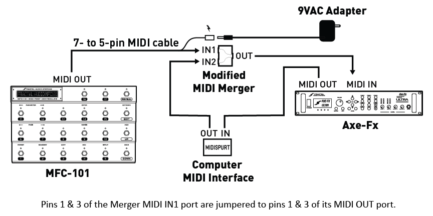
- Credit to Matman for above pic
The Second Method
The second picture is how mine (s0c9) is setup using standard 5-pin midi cables - as I did not have a 7-pin to 5-pin cable.
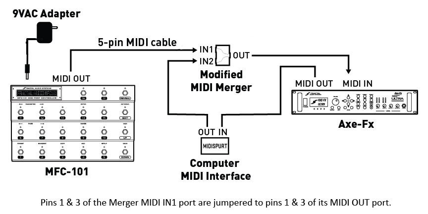
Modified MIDI-MERGE Box
[UPDATE: - (per play4quarters) midisolutions.com can do the custom mod show below, for you. The charged is an addition $20.00 for the mod. If interested contact John Fast - john@midisolutions.com . You can refer to it as the DIN1/3 pass through mod.]
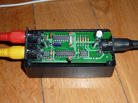
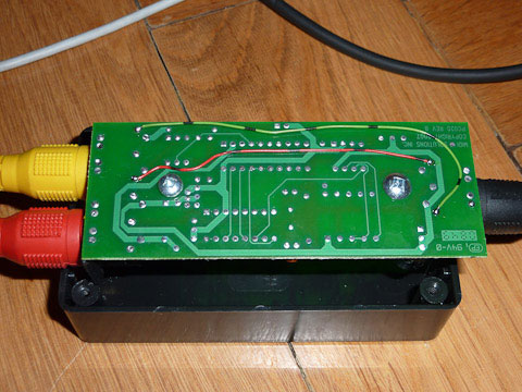
The modification shown below is necessary to allow the MFC and Axe to communicate with each other. Without this mod, the Tuner, Tap Tempo and Patch names will not be displayed on the MFC. The Axe's midi IN port is actually bi-directional, you will need to connect midi ports 1&3 on either the IN1 in IN2 sockets (your choice) to the 1&3 pins on the OUT port of the merge box to make them talk to each other correctly.
"The merger-box has four screws under the "MIDI Solution" Sticker - so don't break your box to get through to the PCB, just pull of the sticker and unscrew the top. Then lift the PCB out of the box - it's not glued or screwed - and solder cables from the IN port (I chose IN2 because phantom power comes from my MOTU) of your choice to the OUT port (Pin 1&3) on the downside of the PCB. Pin 1&3 are the outside pins of the socket.They aren't connected to anything."
- Credit to Michael for the pics below and description inside quotes above
This process should work for most "like" products, assuming you chose not to use the Midi Solutions merge box.
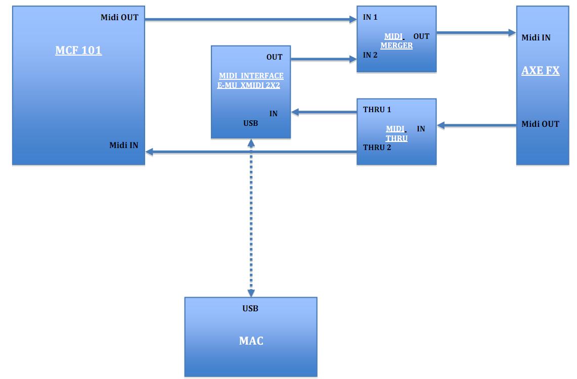
Alternative Solution for Mac/Emu Users
The following solution was provided by Paolo68 for Mac users with and Emu interface.
Per joe1871 - "Anybody else out there looking to get the MFC working with the Axe and your PC get Paolo's doc, and a MIDI Solutions Merger and MIDI Solutions Thru (I got the Quadra Merger and Quadra Thru. Folllow the doc, then launch the Axe PX app. Go in and select the channels you used on your MIDI IF and you have USB working on the PC. No more swapping cables! (Granted I only swapped cables for a couple of days, but it was a PITA that I am glad to be free of)."
