Template:MFC And AxeEdit Working Together
Contents
Getting the MFC-101 and AxeEdit working together
There was a [lengthy] MIDI Merge thread on this subject on the FAS forum, so thought it should be added to the wiki for preservation sake, as I'm sure here are MANY folks who would like to get this working. This page explains what to do to get AxeEdit and the MFC-101 working with the Axe at the SAME TIME.
BASICS
| NOTE: 'This article assumes use of the equipment listed below. Different choices for your midi merger will likely require a different approach.' |
- To get started will need the following equipment:
- midi merge box [eg: Midi Solutions Midi Merge]
- midi interface to PC [eg: M-Audio Anniv 2x2]
- 3 or 4 5-pin midi cables [eg: any standard 5-pin midi cable]
- 7-pin to 5-pin midi cable [OPTIONAL]
THE BIG Picture
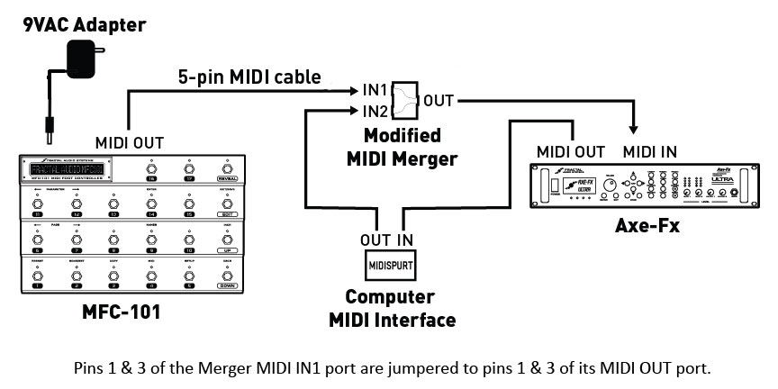
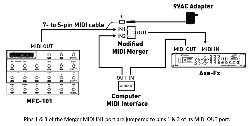
The following TWO pictures show different ways to achieve the same objective. BOTH use the "modified" midi-merger box - which is explained below. The first approach uses standard 5-pin midi cables whereas the second uses a 7-pin to 5-pin cable that supplies power to the MFC.
The First Method
The first picture is how mine is setup using standard 5-pin midi cables.

The Second Method
The second pic (Matman's method) uses a 7-pin to 5-pin midi cable modified to connect the power to the MFC-101.

- Credit to Matman for above pic
Modified MIDI-MERGE Box
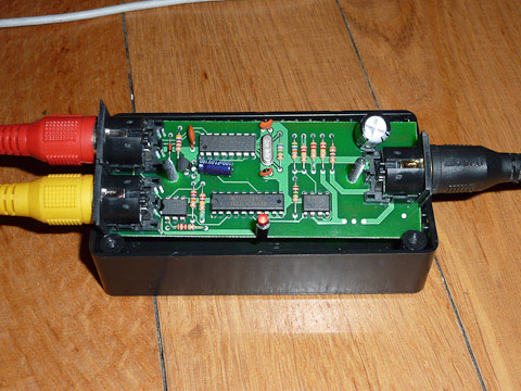
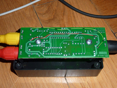
The modification shown below is necessary to allow the MFC and Axe to communicate with each other. Without this mod, the Tuner, Tap Tempo and Patch names will not be displayed on the MFC. The Axe's midi IN port is actually bi-directional, you will need to connect midi ports 1&3 on either the IN1 in IN2 sockets (your choice) to the 1&3 pins on the OUT port of the merge box to make them talk to each other correctly.
"The merger-box has four screws under the "MIDI Solution" Sticker - so don't break your box to get through to the PCB, just pull of the sticker and unscrew the top. Then lift the PCB out of the box - it's not glued or screwed - and solder cables from the IN port (I chose IN2 because phantom power comes from my MOTU) of your choice to the OUT port (Pin 1&3) on the downside of the PCB. Pin 1&3 are the outside pins of the socket.They aren't connected to anything."
- Credit to Michael for the pics below and description inside quotes above
This process should work for most "like" products, assuming you chose not to use the Midi Solutions merge box.

