Difference between revisions of "Getting set up"
Javajunkie (talk | contribs) |
Javajunkie (talk | contribs) |
||
| Line 1: | Line 1: | ||
==Getting Set Up== | ==Getting Set Up== | ||
| − | === | + | ===Getting Set Up=== |
| − | |||
| − | |||
| − | [[Image:RearPanel.jpg | + | '''Rear Panel'''<BR /> |
| + | |||
| + | [[Image:RearPanel.jpg | Left |Figure 4. Axe-Fx rear panel]]<BR /> | ||
1. Input1 - Connect line-level input sources to these jacks. If using the Axe-Fx as an | 1. Input1 - Connect line-level input sources to these jacks. If using the Axe-Fx as an | ||
Revision as of 02:02, 11 June 2007
Getting Set Up
Getting Set Up
Rear Panel
1. Input1 - Connect line-level input sources to these jacks. If using the Axe-Fx as an effects processor use these jacks and be sure to set the INPUT SOURCE to ANALOG REAR in the I/O menu. NOTE: The front panel INSTR input is defeated whenever a plug is inserted into this input.
2. Input2 / Eff. Return - If using the effects loop the output of the effect(s) in the loop are connected here. You can also use this as a generic input by placing the effects loop block in the grid but not connecting anything to the block’s input.
3. Output1 - Main outputs. There are two sets of outputs, unbalanced and balanced. The balanced outputs are intended for use with a mixing board and balanced cables (mic cables). The unbalanced outputs are intended for connecting to a power amp or other unbalanced equipment. The GND LIFT switch lifts the shield ground on the balanced outputs. If you get hum using the balanced outputs flip this switch to isolate the ground.
4. Output2 / Eff. Send - Connect this to the input of the effect(s) in your effects loop. You can also use this as an auxiliary output for on-stage monitoring or other uses.
5. Digital I/O - The IN connector provides 24-bit / 48 kHz digital input to the Axe-Fx. When configured to use the digital input, INPUT1 is defeated and the effects loop is not active (see I/O Configuration). The OUT connectors provide a digital version of the audio from OUTPUT1. The format is 24-bit / 48 kHz. Digital audio output is provided on both RCA and XLR connectors. Digital in is provided on an RCA connector. You can connect and AES digital source (XLR connector) to the RCA digital input jack using commonly available AES to SPDIF adaptor cables.
6. MIDI - MIDI interface. Connect your MIDI controller to MIDI IN. The POWER jack provides power on pins 6 and 7 of MIDI IN allowing phantom powering of pedal boards that support this.
7. Pedal / Footswitch - Pedal / footswitch inputs. Connect your expression pedals and/or footswitches here. Each jack is a ¼" stereo jack capable of supporting an expression pedal or a footswitch (either momentary or latching). When connecting an expression pedal the pedal data can be used to control various parameters continuously such as volume, rate, drive, etc. A footswitch would normally be used to control bypass or preset recall. See the I/O Configuration section for more information on pedal types and configuration.
8. A/C In - Mains power. Connect to a grounded AC receptacle.
Front Panel
Figure 5 shows the front panel of the Axe-Fx.

1. Status / Warning Indicators - These four LED's consist of: EDITED - Lit if the current preset has been edited, reminding you to save your changes. MIDI IN - Lights whenever MIDI data is received. OUT1 CLIP - Lights whenever the digital signal level at OUTPUT1 has exceeded that which is representable by 24-bits. Internally the Axe-Fx uses 32-bit floatingpoint numbers so clipping is virtually impossible. These values are then converted to 24-bit fixed-point numbers prior to being output. If the converted value is greater than that which can be represented by a 24-bit fixed-point number, this will cause clipping of the D/A converter and clipping of the digital output. If the clipping is severe audible distortion may result. Reduce the output level by either turning down the level in one or more of the effect blocks or by turning the master output level down in the layout mixer.
OUT2 CLIP - Lights whenever the signal level at OUTPUT2 has exceeded that which is representable by 24-bits. Reduce the output level by either turning down the level in one or more of the effect blocks or by turning the master output level down in the effects loop mixer.
2. Value / Enter / Exit - The value dial is used to adjust values of various parameters. The ENTER button is used to commit effects to a block, attach controllers and various other activities. The EXIT button cancels dialogs and escapes from various states
3. Navigation - The four navigation buttons allow movement within a page. The PAGE buttons switch between pages.
4. Menu Pressing a menu button brings you to that menu instantly: LAYOUT - This is the effects grid placement and routing menu. There are four pages: EDIT, MOVE, GATE and MIX. The EDIT page is used to place and route effects. The MOVE page allows moving an effect once it's been placed. The GATE page contains the adjustable parameters for the Noise Gate. The MIX page allows overall mixing and panning of the four rows in the grid as well as overall output level adjustment. EDIT - To edit an individual effect, highlight that effect in the LAYOUT>EDIT menu and press EDIT. This brings up the edit pages for that effect. Pressing EDIT again switches to the next effect in the grid. CONTROL - Pressing CONTROL brings up the menu pages for the internal controllers. These are TEMPO, LFO1, LFO2, ADSR1, ADSR2, ENV and MODS. These are discussed in more detail in the controllers section. EFF. BYP - To bypass and individual effect, highlight the effect and press EFF. BYP. The outline of the effect in the grid will change to a dotted line indicating the effect has been bypassed. Pressing the button again will restore the effect. GLOBAL - This brings up the Global parameters menu. There are three pages: OUT1, OUT2, and MIX. These are discussed in more detail in the Global section. TUNER - Pressing this button brings up the tuner display. I/O - This button brings up the I/O Setup menu. This menu allows you to configure the various audio and control options of the Axe-Fx. See the I/O Section for more details. UTILITY - This menu contains various utility functions. See the Utility section for more details. RECALL - Brings up the Recall display and allows you to recall presets using the value dial. STORE - Enters the Store menu allowing naming and saving of the current preset.
BYPASS - Pressing this button bypasses the Axe-Fx. The LED on the button is lit
indicating the bypass state. Press the button again to defeat the bypass. Pressing
this button twice in rapid succession restores all parameters of the selected effect
to their default values.
TEMPO - Tap the song tempo using this button. The LED on the button flashes at
the tempo that was tapped in. The tempo is saved with the preset but may be
overridden at any time. Recalling a preset loads the tempo of that preset. Any
effects set to use tempo will adjust their dependent parameters to the current
tempo.
5. Level Controls INPUT1/2 - These controls set the input levels to the A/D converters. For best signal-to-noise ratio adjust the levels until the top red LED just barely lights on the strongest peaks. For example, adjust INPUT1 so that when you strum your guitar loudly with its volume all the way up the red LED should light only occasionally. Setting the level controls too high may result in clipping of the input causing audible distortion. For guitars with humbucking pickups the INPUT1 control will normally be around the 2:00 position. For single coils you may wish to set this control slightly higher. For best results when plugging line-level devices into an input set the controls at midpoint and adjust the output level of the device so that the red LED barely lights on the strongest signal peaks. The LED’s indicate the signal level at the A/D converter. When the red LED lights the signal into the A/D is 6 dB below full-scale (6 dB headroom). OUTPUT1/2 - These controls set the output level of the Axe-Fx. Adjust these to suit the equipment connected to the outputs. Setting the levels too high may result in clipping of the attached equipment. The Axe-Fx is capable of delivering about +18 dBu maximum with level controls at full.
6. Instr - Plug your guitar into this jack. This input is conditioned especially for use with your guitar. Plugging a line-level device into this input is not recommended as this may cause clipping of the input amplifier. Be sure to set the INPUT SOURCE to ANALOG FRONT in the I/O menu. If a plug is inserted into the INPUT1 LEFT/MONO jack on the rear panel this input is defeated.
Example Connections
Below are examples of the Axe-Fx in various configurations along with explanations and tips on usage.
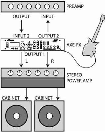
As an Effects Unit with Separate Preamp and Power Amp
The Axe-Fx can be used as an effects processor along with a dedicated preamp and power amp. In this configuration the preamp provides the primary distortion and tone shaping while the Axe-Fx provides effects. By using the preamp in the Axe-Fx’s effects loop you can place effects both before and after the preamp. Certain effects, like wah and phaser, tend to work better before distortion, whereas time-based effects such as delay, chorus, reverb, etc. sound best after distortion. This configuration also allows you to use the Axe-Fx amp simulations as well. In this way you can use the outboard preamp for certain sounds, and the Axe-Fx for others. Be warned, however, after using the Axe-Fx’s amp sims you may find your preamp redundant and just adding unnecessary weight to your rack! Of course you can always use the Axe-Fx between the preamp and power amp, if desired, in the classic post-distortion configuration.
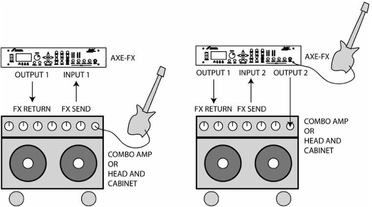
As an Effects Unit with a Combo Amp (or Head and Cab)
Below are two possible configurations for using the Axe-Fx with a combo amp (or head and cabinet). In the first configuration the Axe-Fx is simply used in the effects loop of the amp. The second configuration is more complicated but allows effects both before and after the amp’s preamp stage. In this configuration you are using the amp in the Axe-Fx’s effects loop.
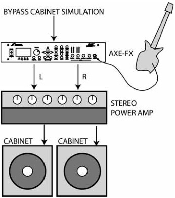
As a Preamp / Processor Into a Power Amp and Guitar Cabinet(s)
In this configuration the Axe-Fx is providing all distortion and tone-shaping. The output of the Axe-Fx is connected to a power amp and cabinets equipped with guitar speakers. Since the cabinets are not full-range, the cabinet simulation in the Axe-Fx should be defeated. This can be done globally via the GLOBAL menu, or perpreset by bypassing the cabinet block or removing it from the signal chain. If the power amp is a tube amp you may want to bypass the Axe-Fx power amp simulations as well. This can be done via the GLOBAL menu, or per-preset by turning the SAG control fully counter-clockwise.
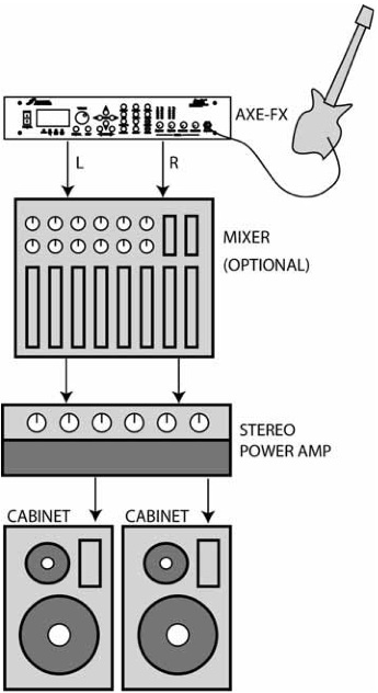
As a Preamp / Processor Into a Full-Range System
In this configuration the Axe-Fx is providing all distortion and tone-shaping. The output of the Axe-Fx is connected to a full-range sound reinforcement system. Since the system is full-range the Axe-Fx’s cabinet simulation should be active. The configuration shown would be typical of using the Axe-Fx straight into a FOH mixer. Your sound man would then send you your sound back into your stage monitor(s). You can also use this configuration without the mixer as a stage rig. Simply connect the Axe-Fx into a power amp and full-range speakers for the ultimate in tonal flexibility.
Recording
Using the Axe-Fx in the studio is straightforward. Simply connect the main outputs (analog or digital) to a mixer, computer, etc.
I/O Configuration
Press the I/O button to access the I/O configuration menus. These menus allow you to configure the audio, MIDI and pedals of the Axe-Fx. Mode Configuration The first page of the I/O menu configures the primary input source. Setting the INPUT SOURCE to ANALOG FRONT or ANALOG REAR configures the unit to slave all clocks to the internal 48 kHz word clock. Setting to DIGITAL selects the DIGITAL input as the main input and slaves all clocks to this bit stream. The Axe-Fx can only run at 48 kHz. If you connect a digital source to the unit be sure that its sample rate is 48 kHz. Set the INPUT SOURCE to ANALOG FRONT when using the front-panel input. This input is conditioned to provide optimum noise performance for use with an electric guitar. Set the INPUT SOURCE to ANALOG REAR when using the rear-panel input. This input is a generic line-level input and works with any line-level source. Audio Configuration The next page of the I/O menu configures the inputs to the Axe-Fx. Select the desired mode for each of the inputs as follows: LEFT ONLY - Use for monophonic input sources. For INPUT 1 use the front panel INSTR jack or the rear panel INPUT1 - LEFT / MONO jack (set INPUT SOURCE as described above). For INPUT 2 use the rear panel INPUT2 - LEFT / MONO jack. In this mode the left input signal is copied to the right channel. L+R SUM - Use when you wish to sum two sources using the LEFT and RIGHT input jacks. STEREO - Select this if your input source is stereo. MIDI Configuration The MIDI page configures the MIDI parameters and preset mapping of the Axe-Fx. The Axe-Fx contains memory for 384 presets. From a MIDI standpoint these presets are arranged in 3 banks of 128 each. To recall presets above 127 your MIDI device must be capable of transmitting a MIDI Bank Select Coarse controller message (controller #0). The value of this message selects the bank (0 - 2). Subsequent MIDI Program Change messages access programs from the selected bank. MIDI CHANNEL - Selects the MIDI channel to which the Axe-Fx will respond. If set to OMNI the Axe-Fx will respond to MIDI messages on all channels. PROG CHANGE - When set to ON the Axe-Fx will respond to MIDI Program Change messages. When set to OFF it will ignore them.
MAPPING MODE - When set to OFF the Axe-Fx will recall the preset given in the
Program Change message. When set to CUSTOM you can set up a custom map
where an incoming number is mapped to a desired preset
MAP FROM - Sets the input MIDI Program Change number that is mapped.
MAP TO - The actual preset that is recalled when the MAP FROM number is received.
NOTE: Mapping is only supported within Bank A (presets 0 - 127).
SYSEX ID - Sets the System Exclusive ID of the unit.
Control Configuration
The CTRL page configures the external control capabilities of the Axe-Fx. Each item
in the list can be controlled by either of the pedals or by a MIDI continuous
controller. To set up the control for an item simply turn the value dial to select the
MIDI continuous controller number (or desired pedal) that will control that item. The
Axe-Fx has a “learn” feature that allows it to detect the controller. Simply select the
desired item to control and press ENTER. Now move the controller and the Axe-Fx
will learn the controller number.
Example
To set the main output volume to be controlled by Pedal1 select OUT1
VOLUME with the navigation buttons. Then turn the value dial to select
PEDAL1. Alternatively press ENTER and then move your pedal connected to
the PEDAL1 jack until the Axe-Fx learns the source.
In the list there are eight external controllers labeled EXTERNAL 1, EXTERNAL 2, etc.
These are the external sources that can be attached to controllable parameters.
The actual source can be either of the PEDAL inputs or any MIDI continuos
controller.
Example
Manual control of effects like Wah requires an external controller to be
attached to the Wah’s CTRL knob. In this example we’ll assume an
expression pedal is connected to the PEDAL 2 input jack. The first step is
to assign PEDAL 2 to an external controller. In this case we’ll use EXTERNAL
1. To do this select EXTERNAL 1 with the navigation buttons and turn the value
dial until PEDAL 2 is displayed (or use the Auto-Learn function). Now when
you attach a modifier to the Wah’s CTRL knob simply select EXTRN 1 as the
control source.
In this example we could have used any of the eight external controllers or any
MIDI continuous controller. The main point to understand here is that there are
eight logical external control sources. Each source is assigned to a physical source
via the CTRL menu page. This source can be the PEDAL inputs or a MIDI continuos
controller. The logical source is then attached to an effects parameter (via the
MODIFIER menu, see the Controllers and Modifiers chapter).
GLOBAL BYPASS - The Global Bypass controller is a special type of bypass control.
Whenever the Axe-Fx receives a Global Bypass controller message it toggles the
state of any effects that were bypassed in the current preset. For example, if a
preset has a Wah in it and that preset is saved with the Wah in a bypassed state
the Global Bypass message would un-bypass it. This controller can be used as a
universal master bypass control that toggles the bypassed blocks for each preset.
Normally you would have to remember what effect is bypassed in a preset and then
send the appropriate controller for that effect. With the Global Bypass, however,
you can use a single controller to toggle effects for each preset on and off. For
some presets you may have a Drive block that you wish to toggle on|off to switch
between rhythm and lead work. For others you may have a Wah or Flanger or
whatever that you wish to toggle. So instead of having to use a different controller
for each preset you can simplify and just use one.
When a preset is recalled the effects are in the bypass state that they were stored
in. Any that are bypassed may then by activated using either their individual bypass
controllers or all may be activated by using the Global Bypass.
EFFECT BYPASS - Each effect in the Axe-Fx can be toggled in and out of bypass
using a MIDI continuous controller. Following the Global Bypass item are the
individual bypass controllers. Simply set the value to the desired controller number
(or pedal number).
Example
To control the bypass state of Flanger 1 use the navigation buttons to select
FLANGER 1 BYP. Then turn the value knob (or press ENTER to
automatically learn) to select the desired controller number. In this example
we’ll use CC# 12. Now whenever the Axe-Fx receives a CC# 12 message
the bypass state of Flanger 1 will be set to the value of the controller.
Note that the Axe-Fx uses negative logic for the bypass state. A controller value of
zero bypasses the effect and non-zero the effect is active. So if the controller value
equals zero, effect off, controller value greater than zero, effect on.
Pedal Configuration
The PEDAL page configures the pedals. The pedals can be used for parameter
control, volume control, effect bypass, preset switching and other purposes. When
used for preset switching the Axe-Fx can change presets without the use of a MIDI
controller.
The two pedal jacks on the back of the Axe-Fx support continuous, momentary or
latching pedals. Continuous pedals are normally used for real-time continuous
control of effect or global parameters (i.e. volume). The other types are normally
used for bypass control or preset switching. It is important to understand how the
various pedal modes operate to use them to the ultimate capability.
To use the pedal for switching operations such as bypass or preset change be sure
to set the pedal type to match the type of footswitch. Momentary footswitches close
a contact while the pedal is depressed. They typically do not "click" when pressed.
Latching footswitches alternate between contacts closed and opened each time
the switch is depressed, they usually click.
Internally the Axe-Fx stores a state for the pedal. For momentary footswitches
depressing the switch toggles the internal state between 0 and 1. When set to
latching the state of the contacts sets the internal state: contacts closed = 0,
contacts open = 1.
Footswitches are normally used to control an effects bypass state or for preset
increment/decrement. Of course one can still assign a footswitch as an external
controller but the "value" from the switch will be either 0 or 1. This may be used, for
example, to change the rate of a Rotary simulator between two speeds, when the
controller is at value 0 the rate would be slow and when at 1 the rate would be fast.
This would be setup using a modifier on the Rotary simulator rate control.
When using a footswitch to control preset recall, a change of state causes a preset
change. For example, if a momentary footswitch is connected depressing the
switch toggles the internal state. This in turn would increment/decrement the
current preset if configured as such. However, if a latching footswitch were
connected but the type is incorrectly set to momentary then the preset would only
change every other time the pedal was depressed as it would interpret the first
press as the pedal being depressed and the second press as the pedal being
released.
If the pedal type is set to continuous it CANNOT be used to control bypass or preset
change. This prevents unwanted behavior in the event the I/O setup is not exact.
Pedal Setup Parameters
PEDAL1 TYPE - Chooses the type of pedal: continuous, momentary or latching.
PEDAL2 TYPE - Chooses the type of pedal: continuous, momentary or latching.
PRESET INCR - Chooses which pedal to use to increment the preset. When the
selected pedal is depressed the next preset will be recalled.
PRESET DECR - Chooses which pedal to use to decrement the preset.
PRESET START/END - When using a footswitch to control preset increment/decrement
the preset recalled will range between these values, wrapping around at the limits.
For example if you wish to use a single footswitch to change presets you could plug
it into PEDAL 2 and set PRESET INCR to PEDAL2. Each time you press the footswitch
the preset will increment by one until the PRESET END value is exceed in which case
it will jump to the PRESET START value. If you wish to cycle through presets 10
through 14 you would set PRESET START to 10 and PRESET END to 14.
PEDAL1 CAL - To calibrate a continuos pedal connected to PEDAL 1 press ENTER
and move the pedal through its full range several times. Press ENTER again when
finished.
PEDAL2 CAL - To calibrate a continuos pedal connected to PEDAL 2 press ENTER and move the pedal through its full range several times. Press ENTER again when finished.


