Difference between revisions of "Concept"
Javajunkie (talk | contribs) (New page: ;'''Concept''' :The Axe-Fx works on the concept of an effects inventory and an effects grid. <BR /> ::''Figure 1. Axe-Fx Concept'' 350px <BR /> The effect...) |
Javajunkie (talk | contribs) |
||
| (2 intermediate revisions by the same user not shown) | |||
| Line 1: | Line 1: | ||
| − | + | ===Concept=== | |
| − | + | ;The Axe-Fx works on the concept of an effects inventory and an effects grid. | |
<BR /> | <BR /> | ||
Latest revision as of 12:46, 13 June 2007
Concept
- The Axe-Fx works on the concept of an effects inventory and an effects grid.
- Figure 1. Axe-Fx Concept
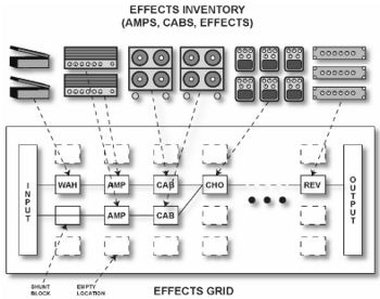
The effects inventory is a virtual stockroom of effects. Effects are removed from the inventory and placed into the effects grid. The grid is a four row by twelve column matrix. Once an effect has been placed in the grid it can be connected to any other effect in an adjacent column. Routing beyond the adjacent columns is not permitted. Figure 1 shows the conceptual model along with a somewhat simple routing. The input feeds the “WAH” block which feeds an “AMP” block which in turn feeds the “CAB” block, etc. A second series path has another amp and cab and this path is added to the first path at the input to the chorus (CHO). Signal flow is always left-to-right. We’ll cover routing in more detail later.
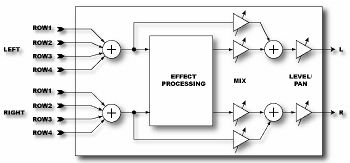
Every effect has a common input-output structure. The input sums the outputs of the effects that feed into the effect. Each effect can have up to four inputs from the previous column. In turn each effect can feed its output to up to four effects in the subsequent column.
- Figure 2. Effect Block I/O Structure
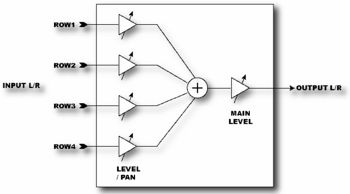
- The Output Mixer (the block labeled “OUTPUT” in Figure 1) sums the signals from the four rows.
- The Output Mixer allows mixing and panning of the four rows and overall level control.
- Figure 3. Output Mixer


