This is the wiki for products made by Fractal Audio Systems, maintained by members of the community.
November 2025: the wiki is updated with AM4 data.
Difference between revisions of "Realtime Analyzer block"
| Line 26: | Line 26: | ||
The RTA block requires an input signal only and doesn't transmit any signal, so its output doesn't need to be connected. | The RTA block requires an input signal only and doesn't transmit any signal, so its output doesn't need to be connected. | ||
| − | =Use to watch the audio spectrum= | + | =Use RTA to watch the audio spectrum= |
The RTA provides detailed visual feedback of the audio spectrum. | The RTA provides detailed visual feedback of the audio spectrum. | ||
| Line 36: | Line 36: | ||
[[image:rta.jpg|300px]] | [[image:rta.jpg|300px]] | ||
| − | =Use to fight feedback= | + | =Use RTA to fight feedback= |
The RTA can point out frequencies where undesired feedback occurs. Turn the Value knob to select the desired band, and the frequency of the selected band will be displayed in the upper left corner. You can then use a PEQ to cut frequencies. | The RTA can point out frequencies where undesired feedback occurs. Turn the Value knob to select the desired band, and the frequency of the selected band will be displayed in the upper left corner. You can then use a PEQ to cut frequencies. | ||
| Line 42: | Line 42: | ||
<blockquote>“Use it to identify problem frequencies or as a spiffy screen saver.” [https://forum.fractalaudio.com/threads/correct-use-of-the-rta-block.141830/#post-1680183] </blockquote> | <blockquote>“Use it to identify problem frequencies or as a spiffy screen saver.” [https://forum.fractalaudio.com/threads/correct-use-of-the-rta-block.141830/#post-1680183] </blockquote> | ||
| − | =Use to test hardware I/O= | + | =Use RTA to test hardware I/O= |
The RTA can be used to test the hardware I/O. For example, to test the Instrument input: [http://forum.fractalaudio.com/threads/output-level.136991/page-3#post-1629752] | The RTA can be used to test the hardware I/O. For example, to test the Instrument input: [http://forum.fractalaudio.com/threads/output-level.136991/page-3#post-1629752] | ||
| Line 54: | Line 54: | ||
# The Input 1 yellow LED should be lit. Red should not be lit. Go to the RTA block Config tab. Set Bands to 128, Window to Blackman. Go to the RTA tab. There should be a narrow spike at 1 kHz (three bands). There should be no other bands showing power except maybe a little noise at the highest bands. The spike at 1 kHz should be about 2 1/4 divisions below full-scale. | # The Input 1 yellow LED should be lit. Red should not be lit. Go to the RTA block Config tab. Set Bands to 128, Window to Blackman. Go to the RTA tab. There should be a narrow spike at 1 kHz (three bands). There should be no other bands showing power except maybe a little noise at the highest bands. The spike at 1 kHz should be about 2 1/4 divisions below full-scale. | ||
| − | =Use to measure devices= | + | =Use RTA to measure devices= |
The RTA can be used to measure the output of other equipment, in conjunction with the [[Synth block]]. For example, to measure the frequency response of an external EQ or distortion pedal, set the Synth block to Pink Noise, send the Synth's signal through the pedal and back again, and use the RTA to measure and see the response. | The RTA can be used to measure the output of other equipment, in conjunction with the [[Synth block]]. For example, to measure the frequency response of an external EQ or distortion pedal, set the Synth block to Pink Noise, send the Synth's signal through the pedal and back again, and use the RTA to measure and see the response. | ||
Revision as of 22:29, 19 December 2023
Contents
Available on which products
- Axe-Fx III: 1 block
- FM3: no
- FM9: no
- Axe-Fx II: no
- AX8: no
- FX8: no
Channels or X/Y
No.
About the RTA
"The RTA is a Fourier Transform." [1]
"The RTA block is a "constant Q" analyzer. White noise increases by 3dB/octave. The two tones are equal in amplitude. Therefore you should see a rising slope on the noise and the tones at equal amplitude." [2]
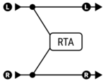
RTA block position on the grid
The RTA block requires an input signal only and doesn't transmit any signal, so its output doesn't need to be connected.
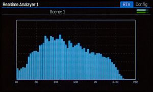
Use RTA to watch the audio spectrum
The RTA provides detailed visual feedback of the audio spectrum.
To view the display, scroll to the RTA block and press Edit.
It also makes for a great dynamic display during performances.
Use RTA to fight feedback
The RTA can point out frequencies where undesired feedback occurs. Turn the Value knob to select the desired band, and the frequency of the selected band will be displayed in the upper left corner. You can then use a PEQ to cut frequencies.
“Use it to identify problem frequencies or as a spiffy screen saver.” [3]
Use RTA to test hardware I/O
The RTA can be used to test the hardware I/O. For example, to test the Instrument input: [4]
- Go to a blank preset.
- Create a chain that connects Input 1 to the RTA block. On a separate row create a chain where the Synth block feeds Output 3.
- Set the Synth Type = Sine, Tracking = Off, Frequency = 1000 Hz.
- Connect an instrument cable from Output 3 (left or right) to the Instrument Input.
- Set the Input 1 / Instrument Level in the I/O menu to 50%.
- Turn the Out 3 Level knob all the way up.
- The Input 1 yellow LED should be lit. Red should not be lit. Go to the RTA block Config tab. Set Bands to 128, Window to Blackman. Go to the RTA tab. There should be a narrow spike at 1 kHz (three bands). There should be no other bands showing power except maybe a little noise at the highest bands. The spike at 1 kHz should be about 2 1/4 divisions below full-scale.
Use RTA to measure devices
The RTA can be used to measure the output of other equipment, in conjunction with the Synth block. For example, to measure the frequency response of an external EQ or distortion pedal, set the Synth block to Pink Noise, send the Synth's signal through the pedal and back again, and use the RTA to measure and see the response.

